Rain Erosion Testing’s NEW Analysis Methodology

Rain Erosion Testing (RET) is an integral part of Leading Edge Protection (LEP) development and certification. It measures the durability of materials to rain droplet impacts. There are different methods to perform RET, including jet impacted stationary samples, solid projectile impact tester, and utilizing a whirling arm tester. In this short article, the main focus will be whirling arm testing. The method consists of one or test specimens mounted on a rotating arm spinning at high velocities. The rotating specimens are exposed to a controlled rain field generated by the testing machine, where rain intensity and droplet size can be controlled. The damage progression is recorded through image acquisition over the complete duration of the test. The image material is then assessed by a specialist to identify the different stages and locations of defects. Finally, the data is visualised in a V-N curve, where V is impact velocity and N is the number of specific impacts. Another common resultant representation of a RET is the incubation period, defined as the time until first damage is observed on the testing sample. There are 3 main failure modes observed during RET testing of LEP products. The first one is uniform erosion and is typical for older coatings. This defect type is characterised by gradual LEP material removal from the high-speed end towards the low-speed end of the testing sample. The second defect development mode is adhesive failure, where the interface between the LEP and the substrate fails due to insufficient adhesive strength. The third commonly seen defect type is local failure around a pre-existing imperfection from manufacturing. This is often the damage mechanism visible on newer LEPs, which are stronger and have improved adhesion to the substrate. Due to the durability of modern LEP products, the amount of water impacts required to cause failure is significant. This leads to either very high rotation speed of the samples, or very long testing times to achieve meaningful testing results. If the rotation speed during RET is too high, it can lead to unrealistic defect modes or test results. This is mainly due to breaking of the droplets to smaller sizes, or vaporisation. On the other hand, longer tests are more expensive and create more data for analysis. Wind Power LAB, in collaboration with R&D Test Systems and DTU – Technical University of Denmark, has developed an enhanced bespoke method for assessment of RET image data collected during testing. In the first stage of the project, which is now completed, we developed an annotation tool that enhances the process for the specialist looking at test images. In the next stage of the project, we will utilise computer vision and machine learning to automatically detect defects/damages on the test imagery. Our initial trials have shown significant potential for the success of such endeavor. Stay tuned for more details on the testing solution software as it develops. It is believed that through this innovation project, Leading Edge Protection coatings and other materials bound for Erosion Testing can be more efficiently and dutifully assessed. In turn, reducing the time to market through productive methodical research and development processes. Hristo Shkalov, Senior Blade Specialist – Wind Power LAB If you are interested in more blog post click here
Leading edge protection – The basics
Leading Edge Protection – Is it Needed? Leading Edge Protection (LEP) is essential for wind turbines with nominal power larger than 2MW. Due to the increased blade length, the tip speed of these turbines can reach up to 90 m/s. That means for sites with annual accumulated precipitation of 0.7 m, the tip area of the blade is hit by an accumulated water column of approximately 10.5 m per year. The introduction of 90+ m diameter rotors coincided with the development of the first large utility scale windfarms in the early 2000s. The combination of high tip speeds and installations in harsher offshore and onshore environments also caused tremendous erosion problems. Older blades have been produced without factory applied LEP and frequently require large repair campaigns of LE damages. With the industry recognizing erosion as a major issue, the race for developing an effective erosion protection solution started. Newer blade generations are now produced with a factory installed LEP in the erosion zone. However, these solutions are not flawless, and repairs are required throughout the lifetime of the turbine. What and Why? To ensure that the most optimal repair/retrofit method is selected, the wind turbine operator should understand the observed damage mechanisms on their site. In the aggressive erosion zone, usually spanning a few meters starting from the tip, the loss of material is driven by environmental conditions. When rain hits the blade surface, a combination from the stress waves propagation, surface fatigue from the repeated droplets impact and the direct deformation at high impact speeds are considered the main reasons for erosion development. In that area, the defect is observed as a continuous stripe of material loss, usually centred around the LE. Outside of the aggressive erosion area, surface defects on the LE develop around pre-existing imperfections in the LEP or the underlying layers. The defects there are characterized by variety in sizes and discontinuity, more uneven depth, random location, and rough edges. The general recommendation for LEP repair is heavy duty solution in the aggressive erosion zone and easy to apply solution for the remaining LE erosion zone. There are 3 main leading edge protection groups – coatings, tapes, and shells. Each of them has its pros and cons, so a good understanding of the erosion condition on a specific site is vital to select the most suitable LEP. LEP Solution Overviews LEP shells are precast with a specific shape for each blade type. They are installed on the blade with an adhesive and the edges are sealed with a sealant to prevent water ingress. This LEP type has the highest level of erosion protection. On the other hand, due to its thickness and shape, it affects the AEP negatively. The solution is suitable for the aggressive erosion zone of wind turbines in harsh environments in their early to mid lifetime. Defects that can be observed on the LEP shells are peeling at edges and overlap zone and delamination at the adhesive interface. LEP tape is supplied in rolls. The adhesive is pre-applied on the LEP tape, however, adhesion promoters and application solutions are required during installation. Edge sealant shall also be applied to protect the edges from water ingress. This solution provides solid erosion resistance, however, it degrades under the effect of UV radiation. It is relatively hard to apply especially around the tip, due to the change of shape there. Moreover, contamination and imperfections in the underlying surface might cause failure of the LEP tape adhesion. Defects on this LEP type include chipping, peeling and scratches from impacts with sharp external objects. LEP coating is characterised by higher elasticity and flexibility than the normal paint applied on the other areas of the blade. The solution is suitable for combination with LEP shells, covering the erosion area outside the aggressive zone. The application process requires a well executed surface preparation. Insufficient sanding or contamination would greatly impact the adhesion quality of the erosion resistance. Another defect enabler for the LEP paint is the propagation and interaction of the compressional waves from the raindrop impact, which can cause delamination in the interface of the LEP and the underlying surface, or between two layers of LEP coating if the solution is not single layer. Conclusion Leading Edge Protection is a critical component to protect the longevity of wind turbine blades. Without proper care and maintenance, cosmetic issues on the leading edge of wind turbine blades can turn into production robbing problems and eventually structural damages that may cause catastrophic failures. If you are unsure of the status of your blades, options in the market, or need guidance about leading edge protection – reach out to an expert! Hristo Shkalov, Senior Blade Specialist – Wind Power LAB Interested in other blog topics. Click here
Replace or Repair? – Exploring Wind Turbine Blade Failures
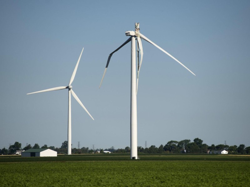
Critical blade defects leading to failure of blades can be caused by excessive force or fatigue damage. This poses a significant risk and creates extreme economic impact for a wind turbine owner. Therefore, it is important to ensure wind turbine blades (WTBs) last their full designed lifetime. Blades can fail via different types of failure modes. This is highly dependent on the individual blade design as selected by the Original Equipment Manufacturer (OEM). Failures can be related to design, manufacturing defects, environmental factors, lightning strikes, external impacts, and fatigue. These damages will lead to complex blade repairs or full blade replacements. To understand if a blade should be repaired or replaced, first the blade must be investigated after a structural damage is detected. In a Root Cause Analysis (RCA) investigation, different initial hypotheses are enlisted if failure is related to design, manufacturing, fatigue, or control issues. Therefore, the blade design type, the location of the failure, defect characteristics and SCADA data should be investigated thoroughly to proximate the cause. Initially, the structural damage in the final failure should be categorized if it is a: · Potential initiator of the failure: Key evidence to point out that the potential initiator damages are the defined patterns of cracks, delamination surrounding the damage, and stress whitening of laminate. · Damages caused by the damage initiator: The damage initiator can cause effect on its neighboring structures. This has an undefined crack pattern and shows more of a laminate tear appearance which occurs during collapse. Once damages are categorized, more in-depth investigation will be applied to the potential initiator of the failure if it is associated to manufacturing, fatigue or irregular loading caused by faulty control systems. Therefore, it is of importance to build a failure scenario supported by facts, carry out a proper investigation which highlights the failure mechanism, and understand how it has progressed leading to the final failure. To restore the blade structural integrity, the repair must consider the following: · Damage severity level: specification of how much the damage has affected the blade in terms of material damage and extension of area affected, i.e., how big, and deep the damage is. · Damaged region: correlated to severity level but, it is important to understand that blades are composed of different structural components. If these structural regions are affected, then severity level becomes higher. · Aerofoil geometry requirements: since blades are designed with complex geometry, ensuring that aerodynamic efficiency is reached to cultivate maximum power from the wind resource. If the blade’s structural components are affected, and if the damage extension is too big and deep, then a repair is less likely to be successful. It is important to highlight that when a repair is performed, it must restore the blade’s structural integrity and should endure loads during the blade’s remaining lifetime. Taking these considerations into account, a repair scope can be built where other factors are accounted for, including material and tools requirement, labour, logistics and weather. These factors will be the base of the cost of the repair. That is why it is highly suggested that a repair cost breakdown must be requested, to mitigate the cost of repair in comparison to the cost of blade replacement scenario. When deciding if a repair of a blade is feasible, it is important to determine the affected areas of the blade. If the damage is confined to the blade shells, it is in most cases possible to repair the blade. The main driver of repair time and complexity is determined by the area the defect covers. If the defect is located at the blade beam, root, and web structure, it affects load carrying parts of the blade. This increases the complexity and size of a repair significantly, as the overlap between laminate layers in the repair ensures that the repair can handle the loads in the structural parts of the blade. To determine if a repair exceeds the value of the blade, it is necessary to establish the position of the blade damage, effect on the blade structure and size of the repair. Then, repair time and cost are estimated and matched against cost of a blade replacement. If a replacement has been determined as the best course of action, then it is essential to find matching blade(s) that balance with the remaining blades on the turbine. Turbine blade manufacturing is still to a larger degree a handcraft, it is therefore common to encounter discrepancies between blades of the same type. This is due to the manufacturing process, where the glass fiber layers are impregnated with epoxy resin. It is common to see difference in saturation levels of composite laminates, and resin pools in the blades are also an expected occurrence during the manufacturing process. This creates variation in blade weight and load distribution across the blade span. Therefore, it is a good indication that if two blades match in weight but, the blade center of gravity (CoG) and loads at the blade root, also known as root bending moment (RbM), need to match for the blade set to balance. If a selected blade does not fit to the other blades in the set, it will cause rotor imbalance that causes unwarranted loads to the blades, bearings, and the drivetrain. It is possible to adjust some discrepancy in the blade attributes using weight blocks or ballast boxes inside the blade. These weights are often placed at the midspan of the blade. There is a limitation to the amount of weight that is possible to add, as it increases loads locally in the weight position. This can cause early life fatigue if the loads exceed the allowed threshold. It is therefore true that not all blades are possible to matched if their weight, CoG or RbM is exceeding the adjustment range of the blade set. Authors – Wind Power LAB Morten E. Handberg, Chief Blade Specialist at Wind Power LAB https://www.linkedin.com/in/morten-handberg-24196b11/ Aura Vanessa Guzmann, Senior Blade Specialist at Wind Power LAB https://www.linkedin.com/in/aura-venessa-paguagan/
Lightning Protection System
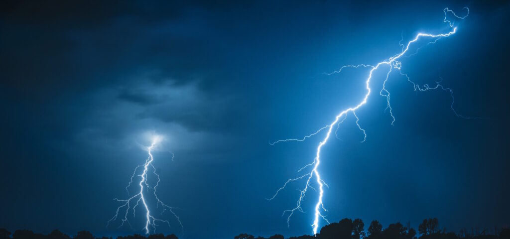
By Morten Handberg, Chief Blade Officer at Wind Power Lab; and Nick Baker, Associate Director at Global Risk Solutions. Lightning damages to wind turbine blades account for a significant percentage of operational onshore wind claims. Based on more than 3,500 renewable losses, GRS’ loss database indicates that lightning damage accounts for 60% of operational blade losses and almost 20% of operational wind losses overall. In our experience, we have found that the levels of damage observed can be highly variable – from repairable ‘puncture’ like damage, to the blade’s destruction. This white paper focuses on the blades’ lightning protection system (LPS). This white paper focuses on the blades’ lightning protection system (LPS). We are often asked how these systems work and why severe blade damage can still occur. Here we will give an overview of how a typical LPS works and provide our best practice recommendations. LPS description The LPS is a passive lightning protection system, ensuring that lightning strikes hitting the blade is transferred to the grounding. The systems are tested in accordance with the IEC 61400-24 standard. Dependent on the test tier, the system is designed to handle 100-200kA, without significant system wear. The diagram below shows a typical LPS: LPS Components Receptors. The receptor is a component made from metal, either copper or equivalent current transferring metal alloy. It is designed to attract lightning and transfer the load to the receptor block. The receptor is a replaceable component that is mounted post blade production. Risks of failure are worn receptor base or missing connection to the receptor block. Visual inspection can be used to determine a receptor’s condition. Receptor Block. To connect the receptor with the down conductor cable, an aluminium block is cast into the blade with the down-conductor during blade production. A replacement requires a complex laminate repair as the blade laminate must be removed before the block can be accessed. Common issues involve detachment or missing connection to down conductor cable or receptor. A visual inspection cannot detect a lost connection between the receptor block and down conductor cable. Instead, it can be checked with a resistance measurement. Down conductor cable. The design of the cable varies between the different OEM’s, including copper mesh, solid copper cable, linked aluminium plates and solid cable. The cable is centered on the web of the blade. It can be located on both LE or TE side dependent on the OEM design. Repair is possible but complex. Failure types include missing connection to root terminal, or receptor block and cable separation due to fatigue. connection to the root terminal can be checked with an internal visual inspection, which can be performed without entering the blade. Detecting separation of the down conductor cable is possible with a dedicated internal inspection. Root connection. The root connection is designed to transfer the load from the cable to the bypass system. Failure modes at the root terminal include missing connection, which is not designed to carry electrical current. Lightning transfer system. The design of the transfer system varies between the different OEMs. It can be spring coupling, brushing, or spark gap. These systems are designed to receive limited wear from lightning transfer; thus, they occasionally need replacement. A defect that can be observed in the lightning transfer system is insufficient contact in the case of the brush or coupling, or too large distance in the case of the spark gap. Visual inspection can detect such defect; moreover, for brush and coupling designs a resistance measurement can be performed. Our LPS Recommendations Operators can reduce the risk of lightning damages by conducting regular scheduled LPS inspections. A maintenance strategy must be in place to define scope and inspection frequency. Receptor wear and sealant damages can be observed during a standard external inspection; down conductor connection to the root terminal can be visually inspected during planned turbine maintenance; the integrity of the down conductor can be examined during an internal blade inspection. During an LPS inspection, it is important to: Check the surface condition of the receptor. If material wear exceeds below the blade surface, a replacement is required. Check that the connection between the down conductor, root terminal and lightning transfer system is intact. If scorching and/or arching is detected near the root terminal, the connection is likely missing or par7al. Check the surface condition of the transfer system. Too large spark gap or poor connection conditions could cause undesired lightning jumps to other parts of the turbine. Major failures due to a lightning strike to the blade can be divided into two main categories: A “force majeure” event is described as lightning with an unusually high current that exceeds the design limitations of the LPS. A defect in the LPS leads to a reduced ability to transfer the lightning or a missing connection, thus reducing the likelihood of lightning traveling through it safely to the ground. The risk of the la]er can be reduced by having a maintenance schedule in place for blades. This would also prevent some fatigue damages from going unnoticed. While the “force majeure” damages are hard to influence, defects due to malfunctioning LPS can be minimised with a more focused effort from the industry. At present, Germany is the only country with meaningful legislation about the inspection of an LPS – it should be inspected every four years as a minimum. For comparison, turbine owners in Denmark are only obliged to inspect the LPS of their turbines when they have reached 20 years in operation. Installing lightning trackers on sites can help to collect more parameters for lightning that are hitting the turbines. The wind industry will benefit from having easy access to accurate lightning data from the local site when assessing damage from lightning strikes. Ultimately, from an insurance perspective, the breadth of cover commonly offered by a typical onshore wind policy regarding defects coupled with the difficulty in determining the strength of a lightning strike can make it challenging to apply any adjustments to the claim. However, the