The Lightning Protection System (LPS) is a passive lightning protection, ensuring that lightning strikes hitting the blade are transferred to the grounding.
The systems are tested in accordance to the IEC 61400-24 standard.
Dependent on the test tier the system is designed to handle 100-200kA, without significant system wear.
Receptors
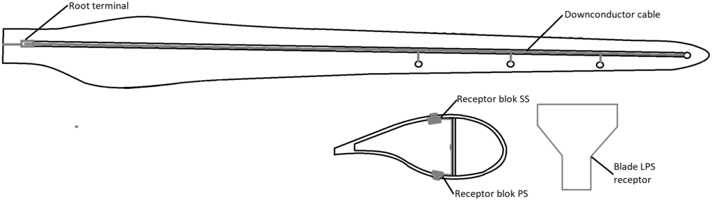
The receptor is a component made from metal like copper or equivalent current transferring metal alloy. It is designed to attract lightning and transfer the load to the receptor block. The receptor has a conic screw below the base that ensures contact to the receptor block. The receptor is a replaceable component that is mounted post blade production. On older blades the tip receptor can be a massive copper piece taking up the outer 20cm of the blade tip.
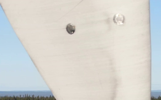
Risks of failure are worn receptor base or missing connection to the receptor block. The wear mechanisms include arching of the receptor base from lightning attachments and corrosion from water ingress between the receptor and receptor block. Visual inspection can be used to determine the condition of a receptor. Scorching and deformation are the most common signs of wear from lightning on the receptor base. Lightnings will also remove some material of the receptor base over time. If material removal proceeds below the blade surface, the receptor will have a reduced attractiveness to lightning.
Missing sealant allows water ingress between the receptor and the receptor block, which can cause corrosion and damage to receptor block over time.
Lightning Protection system receptor block
To connect the receptor with the down conductor cable, an aluminum block is cast into the blade with the down-conductor during blade production. Replacement requires a complex laminate repair as the blade laminate must be removed before the block can be accessed. During post processing of the blade the receptor hole is drilled along with the thread for the conic screw.
Risk of failure is detachment or missing connection to down conductor cable or receptor. Missing connection to the receptor can be deducted from damaged or missing sealant around the receptor and corrosion of the two components. Another cause for imperfect connection between the block and the receptor is if the receptor has been screwed at an angle to the block, causing only partial contact, thus reduced capacity to safely transfer lightning. A missing connection between the receptor block and down conductor cable cannot be detected by a visual inspection. Instead, it can be checked with a resistance measurement. This type of check is recommended only as investigation to locate defect in a malfunctioning system and not as part of general inspection.
Down conductor cable
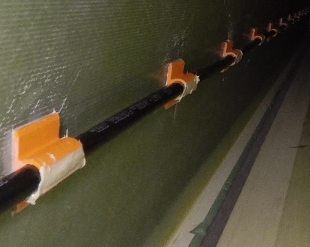
The design of the cable varies between the different OEM’s, including copper mesh, solid copper cable, linked aluminum plates and solid cable.
The cable is centered on the web of the blade, it can be located on both LE or TE side dependent on the OEM design. The cable is cast into the blade during production. Repair is possible but very complex and due to a clamping device changing shape of the cable the blade has additional risks of wrong lightning attachments post repair.
If any carbon is used in the blade to increase the structural strength, it is important that the carbon is included in the LPS to avoid high difference in electric potential between the cable and the carbon laminate. If the carbon is not included, it must be thoroughly checked that it does not provide a risk of lightning jumping internally in the blade.
Failure types include missing connection to root terminal, or receptor block and cable separation due to fatigue. Connection to the root terminal can be checked with an internal visual inspection, which can be performed without entering the blade. Detecting separation of the down conductor cable is possible with a dedicated internal inspection. A skilled technician or internal drone can reach 1/3 into the blade, while a sewer crawler can inspect until a few meters from the tip. The most detailed inspection is achieved by a technician or drone inspection.
Root connection
The root connection is designed to transfer the load from the cable to the bypass system. Blades are equipped with a slipring close to the root. The down conductor cable is connected to the slipring via a connection bolt through the blade laminate or via the backplate.
Failure modes at the root terminal include missing connection to the down conductor cable. If no connection is established lightning would seek other paths to the ground, risking damage to the laminate or drivetrain, which is not designed to carry electrical current.
Lightning transfer system
The design of the transfer system varies between the different OEMs. It can be spring coupling, brushing, or spark gap. The brush and coupling designs are made to have as minimum partial contact from blade to grounding system at all times during operation. These systems are designed to receive limited wear from lightning transfer. The spark gap will transfer the load through an arch between the slipring and the lightning rod. Thus, significant wear could be expected, leading to an occasional need of replacement.
The defect mode that can be observed in the lightning transfer system is insufficient contact in the case of the brush or coupling, or too large distance in the case of the spark gap. In both ways the result would be a less effective, or completely dysfunctional LPS. Visual inspection can detect such defects, moreover for brush and coupling designs a resistance measurement can be performed, if there are doubts for the functionality of the system.
Lightning Protection System measurement
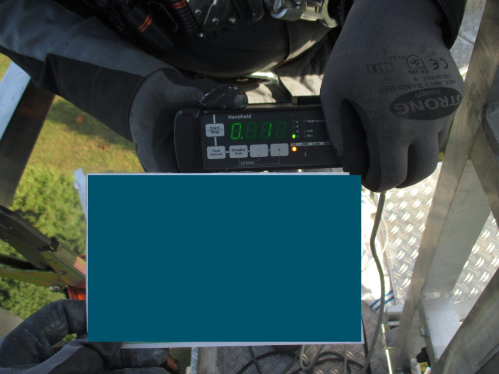
The currently used method of determining whether an LPS is functional is by conducting a resistance measurement. It is performed by connecting multi-meter probes to the two ends of an LPS, essentially creating a closed circuit. To check the functionality of the system within a blade, you must connect one probe to the tip receptor and one probe to the root connection. To check the functionality on turbine level, you must connect one probe to the tip receptor and one probe to the earthing system at the tower base. Performing the measurements between different components of the LPS can help localising the damaged part. For example, if no connection is established during a resistance measurement on blade level from the tip receptor on the SS to the root connection, and a 25mΩ are measured from tip receptor on PS to the root connection, it can be deducted that the damaged part of the LPS is between the tip receptor on the SS and the tip receptor block.
It is worth to note that for blades with spark gaps the turbine level functionality cannot be checked in the mentioned method, as there is no physical connection between the part of LPS in the blade and the one in the tower.
Reporting
The resistance measurement will determine if a connection between the receptor and root connection is present. A common measurement for a 40-45m blade is in the region of 25mΩ, and a full measurement of the grounding system should not exceed 1Ω.
NB! For the LPS in the blade OEMs accept between 1-10Ω as part of their factory QC.
NB! For the full grounding system OEMs accept up to 10-50Ω as part of their commissioning check.
Limitations
An LPS inspection will determine if there is a connection between the receptor and the root connection. However, it is not able to determine the quality of the connection, or point to the error location, as even very limited and weak connection points due to partial separation of the LPS or cable fractures will not show from a resistance measurement. As the resistance is a measure of the system’s opposition to the current and not ability to transfer current. A flaw in the system would have a very little contribution to the resistance, but a significantly reduced ability to transfer current. Therefore, even a system with a resistance measurement of 25mΩ, could cause a major damage during a lightning strike due to a partial connection.
Recommendation
Operators can reduce the risk of lightning damages with conducting regular scheduled inspections of the LPS. A maintenance strategy must be in place to define scope and inspection frequency. Receptor wear and sealant damages can be observed during a standard external inspection; down conductor connection to the root terminal can be visually inspected during a planned turbine maintenance; the integrity of the down conductor can be examined during an internal blade inspection.
During an inspection it is important to:
- Check the surface condition of the receptor, if material wear exceeds below the blade surface, a replacement is required
- Check the that the connection between the down conductor, root terminal and lightning transfer system is intact. If scorching and/or arching is detected near the root terminal then it is likely that the connection is missing, or it is only partial.
- Check the surface condition of the transfer system. Too large spark gap or imperfect connection conditions could cause undesired lightning jumps to other parts of the turbine
Large failures due to a wrong lightning attachment to the blade can be divided in two main categories. The first category is due to a “force majeure” event, which is described as a lightning with unusually high current that exceeds the design limitations of the LPS. The second category is due to a defect in the LPS, which leads to a reduced ability to transfer the lightning. Or a missing connection along the system, thus reducing the likelihood of a lightning traveling through it safely all the way to the ground. The risk of the latter can be reduced by having a maintenance schedule in place for blades. This would also prevent some fatigue damages from going unnoticed.
While the “force majeure” damages are hard to influence, defects due to malfunctioning LPS can be minimised with a more focused effort from the industry. In the present, Germany is the only country which has meaningful legislation about the inspection of an LPS – namely it should be inspected every 4 years as a minimum. For comparison, turbine owners in Denmark are only obliged to inspect the LPS of their turbines, when they have reached 20 years in operation.
Installing lightning trackers on sites can help collecting more parameters for lightning that are hitting the turbines. The wind industry will benefit from having easy access to accurate lightning data from local site when assessing damage from lightning strikes.
Want to learn more?
Don’t be a stranger – Feel free to reach out by clicking here