
Root cause analysis for wind turbine blades
What is a root cause analysis? A root cause analysis (RCA) is a systematic process used to identify the underlying causes of a problem or failure. When it comes to wind turbine blade failures, conducting an RCA is crucial for several reasons. Firstly, wind turbine blade failures can have significant consequences, both in terms of safety and financial impact. Understanding why these failures occur is essential for preventing future incidents and ensuring the continued operation and safety of wind turbines. An RCA involves digging deep into the factors contributing to the failure. This often requires collecting and analyzing data from various sources, including maintenance records, inspection reports, and operational data. By examining these sources, analysts can identify patterns, trends, and anomalies that may shed light on the root causes of the failures. Identifying the root causes of wind turbine blade failures is not always straightforward. It may involve looking beyond immediate or surface-level factors and considering broader issues such as design flaws, manufacturing defects, material fatigue, environmental conditions, or human erro How do engineers start the root case analysis for wind turbine blades? Upon receiving a request for a root cause analysis, our team of proficient engineers initiates an investigation. This begins with a Request For Information (RFI), where we examine data pertaining to the damaged wind turbine blade. Based on the information our engineers analyze the data to formulate a strategy for the RCA process. What are the reasons for blade failures? Wind turbine blade failures can be caused by a multitude of factors, each of which requires careful examination to understand its role in the incident. These factors span a wide range, including environmental influences such as lightning strikes, hailstorms, and sudden changes in wind direction, as well as damages induced by fatigue, human error, or issues related to production quality.Depending on the nature of the failure and the available data, we may proceed solely based on the information provided in the RFI, through remote inspection methods, or by conducting an onsite assessment. Our dedicated blade team is adept at handling each scenario with precision and expertise. The process of investigation can vary depending on factors such as the nature of the failure and the availability of data. In some cases, it may be possible to proceed solely based on the information provided in a Request for Information (RFI), leveraging remote inspection methods to gather additional data. In other instances, conducting an onsite assessment may be necessary to obtain a more detailed understanding of the situation. Regardless of the approach taken, our dedicated blade team is equipped with the expertise and experience to handle each scenario with precision. Whether it’s analyzing remote data, conducting onsite inspections, or interpreting complex findings, our team is committed to delivering thorough and insightful assessments to support effective decision-making and problem-solving. The handover meeting: Ensuring Transparency and Reliability As part of our dedication to delivering an impartial assessment, we prioritize transparency and reliability in our findings. To ensure a comprehensive understanding of the wind turbine blade failure, we will schedule a handover meeting to discuss all the insights uncovered in the report. Want to learn more – Check out this webinar https://www.youtube.com/watch?v=xmVsALIWx1Q Want to get in contact? Feel free to contact us by clicking here
Edgewise Vibrations
Wind turbines (WTs) are complex structures that are required to operate under varying weather conditions. Their blades must be able to withstand hurricane-level winds, and gusts with sudden direction changes. Additionally, they must be stiff enough to avoid high deflections that would lead to blade-tower impacts. It is therefore understood that WTs are dynamic systems that face complex aeroelastic phenomena. Edgewise vibration is such a phenomenon, and it’s the focus of this article. Under specific conditions, this aeroelastic resonant phenomenon can potentially inflict significant damage to the turbine. The vibrational modes of a structure represent the patterns or shapes in which the structure will vibrate in when it is subjected to excitation. In WTs, specifically focused on their blades, three main vibrational modes are distinguished: flapwise, torsional and edgewise. The edgewise mode is characterized by the movement of the blades in the edgewise direction. Figure 1 showcases the edgewise displacement of the blade through time. Figure 1: Blade edgewise displacement in time (Malkin & Griffin, 2016). Want to keep reading? Request a copy of our full white paper report below to access the full content. We have extensive reports and documentation expanding on our blog post topics, written by our own in-house experts. To keep reading, submit your interest below and we will send you a full PDF copy of our report to your email address.
Adhesion Failures in Wind Turbine Blades

Adhesives are widely used material on wind turbine blades, as they are used to bond various blade components during manufacturing process. During blade component assembly, adhesive materials based on design specifications are applied to joints in between shear web to spar cap, trailing edges, leading-edge bites, root, and tip joints, according to wind turbine manufacturer’s application method and blade design. It is important that proper bonding is achieved in these joints to ensure proper load transfer in between adherends and to ensure blade’s structural integrity in the long run. Common errors in adhesive joint Common errors in adhesive application arises from improper surface preparation (surface cleaning and treatment to avoid contaminants), incorrect cure and mixing ratios, insufficient/inconsistent adhesive material thickness, incorrect adhesive material selection (poor wetting ability), and poor adhesive storage and handling. Not all of these common errors can be visually inspected, therefore proper documentation of manufacturing steps for adhesive applications must be specified, including the list of material suppliers. OEMs must also conduct a separate quality check on their suppliers as material deviation causes unintended deviation from blade design and certification. Insufficient quality control leads to undetected adhesive defects. Therefore, proper quality control measures and documentation (QA procedures including visual, NDT inspection, etc.) are required to ensure that quality standards are achieved according to blade design and acceptable tolerances (validated by blade test and finite element simulations), before putting the blades into service Classifying failure modes in adhesion joints In a blade failure, the blade’s adhesive joint quality is inspected and checked if the joint failed in the following main failure modes defined by ASTM D5573 [1]: Adhesive Failure: Rupture of the adhesively bonded joint, such that the separation appears to be at the adhesive-adherend interface. Fibre reinforced polymers (FRP) and adhesive surfaces may have shiny appearance and there is no evidence that any adhesive or FRP, or both, have transferred to the surface [1]. Cohesive Failure: The separation is within the adhesive [1]. Occurs due to high thickness and/or material deviation of adhesive, making longitudinal strain in the mid-plain section high and fail in that location. Fibre-Tear Failure: Failure occurring within fibre reinforced polymers (FRP) matrix, characterized by the appearance of reinforcing fibres on both ruptured surfaces [1]. Adhesion Failures in Wind Turbine Blades If fibre-tear failure is observed after blade failure, it is likely that these regions of fibre-tear are secondary effect of main cause of failure due to strong adhesion bond in between adhesive-adherend interface pointing to good adhesion. Chemical testing and microscopic analysis can be required to classify adhesive and cohesive failure type (or mixed failure mode) in order to understand and validate if manufacturing/design related defect exist. A proactive approach is required in order to lessen the risk of adhesion failure in blades, and this includes following points of recommendation: Request of detailed quality control documentation that includes information such as quality control procedure that must adhere to standard practices which includes information on type of control procedures applied and blade locations where QA is applied. End-of-warranty internal and external blade inspection to catch, claim, and repair (if necessary) adhesion defects in advance. Continuous internal and external inspections of a subset of the blades within a windfarm to track and detect any defect development before significant effect to the blade integrity. Reference: [1] ASTM D5573-2019: Standard Practice for Classifying Failure Modes in Fiber-Reinforced-Plastic (FRP) Joints Feel free to contact us by clicking here
Wrinkle Formation and Risks in Composite Materials
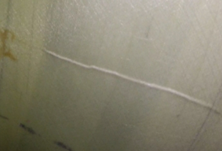
Wrinkle Formation and Risks in Composite Materials – Wrinkles refer to undulations or surface irregularities that manifest as visible folds or creases on the outer layer of a composite structure. These imperfections are typically the result of non-uniform deformation, or stresses during the manufacturing process or service life of the composite material. Wrinkles can occur in various forms, such as small ripples, waves, or more pronounced folds, depending on the specific conditions and factors influencing their formation. The presence of wrinkles in the lay-up of composite materials is undesirable as they can compromise the structural integrity of the final product. Wrinkle Formation and Risks in Composite Materials Wrinkles are described as wave-formed plies and/or fiber deviations from straight alignment in UD laminate. Fiber misalignment can occur on UD plies especially at the transition area which can cause wrinkling. UD plies must be placed 0° from blade length axis. Wrinkles can manifest during the layup, resin infusion and curing phases, posing risks to the structural integrity of composite materials. A wrinkle may also occur in butt joints in between core materials, also known as core gaps. Wrinkles can form both transversely on the UD fibers and longitudinally. Transverse wrinkles pose a higher risk of damage to the blades as they tend to introduce weakness in the laminate, by reducing its tensile performance. As they can disrupt the fiber alignment, the stiffness of the material is compromised, hence negatively influencing the load carrying capabilities of the structure. Transverse wrinkles can contribute to interlaminar shear failures, compromising the bond between adjacent layers in the laminate. This reduction in interlaminar shear strength can lead to delamination, further weakening the structure. The last stage of the transverse wrinkle propagation is the formation of transverse cracks along the defected surface, which can lead to critical damage on the blade. While longitudinal wrinkles can also impact the performance of unidirectional fiber laminates, they are often considered less critical because they align with the primary load-carrying direction of the fibers. The structural consequences of transverse wrinkles are more pronounced, making them a greater concern in terms of potential mechanical failure and compromised performance in unidirectional fiber-reinforced composites. Wrinkle development along a blade Defects that are introduced as outcomes of wrinkle existence can be linked to the load magnitude that is experienced on a localized level. In other words, as the load magnitude is much higher towards the root of the blade compared to further towards the tip, it is more likely for a defect to propagate at the root and hence appear earlier in the lifetime of the blade. It is therefore common for a wrinkle to develop to a delamination or a crack during the first few years of operation if it is located towards the root. For wrinkles that are located further out towards the tip which are exposed to lower fatigue loads, the defect propagation is expected to progress at a slower pace and the damage is likely to initiate or develop at a later stage of the blade lifetime. Despite the risk of introducing blade damage, wrinkle-related defects can be mitigated proactively if an internal inspection regime is in place. Regular internal inspections can help keeping track of the defect development and/or propagation and assist as a decision-making tool on their criticality and evaluating if they require repairing. Wrinkle detection Fortunately, as with other blade defects, wrinkles can be detected in different stages of the blade’s lifetime. Different methods can be used to detect wrinkles in blades after manufacturing and during operation. Factory QC: After the manufacturing process, load carrying components of thick laminate (e.g., spar caps) are inspected with UT scanning to detect for laminate anomalies such as air voids, inclusions, and air pockets, but also more structurally risky defects like wrinkles. Laminate shell structures are inspected visually for wrinkles post-manufacturing. Operation: During operation, regular internal inspection campaigns can be very important in assisting with wrinkle detection and propagation monitoring. Wrinkles that are located on laminate shell structures and at the edges of the spar caps transversely can be captured during internal inspections. Conclusion Wrinkle formation is a critical issue that threatens the longevity of wind turbine blades. Without proper QC procedures on a factory level that can identify wrinkles in an early stage, prior to operation, these defects can propagate to forming cracks that based on their location can result in catastrophic blade failure. It is important that the owner actively participates in the factory QC process through reviewing the inspection method and results to ensure that no sub-surface wrinkles are present in the spar caps. The next important step regarding wrinkles and limiting their risk for the structural integrity of the blade is during the EoW inspections. During the inspections, any overlooked wrinkles on the shells and webs from the factory QC or any wrinkles that were considered within tolerances and started developing shall be observed. Wind Power LAB can assist turbine operators in both abovementioned important stages of a turbine blade cycle. Feel free to contact us by clicking here
Successful End of Warranty campaign for your wind turbine blades
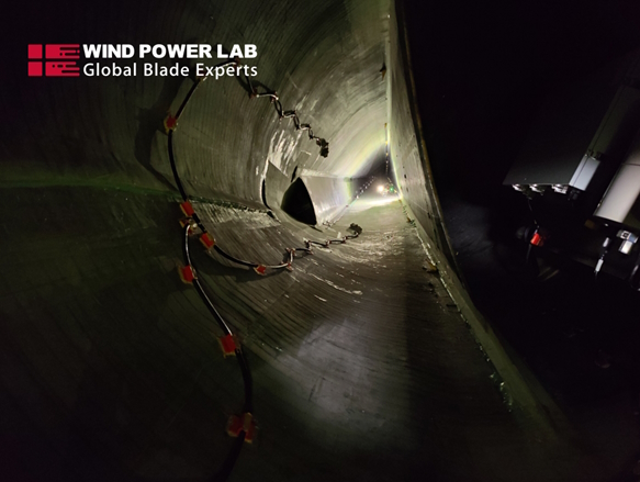
Wondering about the key to a successful End of Warranty (EoW) campaign? It starts with strategic planning. Our approach involves scheduling internal and external blade inspections close to the end of the warranty date, allowing possible defects to develop while maintaining ample time for in-depth assessments and data analysis. External Inspections Get to know the external surface condition. This includes leading edge protection performance, erosion development rates, and detection of structural damages in the outer laminate layers, lightning protection system, potential lightning attachments, and the condition of receptors and add-ons. Internal Inspections We detect manufacturing nonconformities, early-life fatigue damages, and defects in adhesive bond lines, ensuring a comprehensive evaluation. Benefit from Our Analysis and Maintenance Actions All the value comes with our in-depth assessments. We provide precise maintenance actions for each damage, facilitating a smooth transition with detailed claim documents. Wind Power LAB defines the best recommended actions for every defect group. Beyond the immediate technical scrutiny, there exist economic imperatives in documenting necessary repairs. The end of warranty documentation package becomes a bulwark against unexpected costs post end of warranty, ensuring a more predictable financial trajectory. Guiding You Through the End of Warranty Journey Navigating the complexities of a wind farm transitioning out of warranty can be daunting. Drawing from our extensive experience, Wind Power LAB has effectively executed numerous end-of-warranty campaigns for clients globally, providing unwavering support throughout the entire process. Trust Wind Power LAB to be your dedicated guide, leveraging our expertise and cutting-edge tools that empower you to take charge. We are committed to assisting you at every stage, guaranteeing the sustained longevity and optimal performance of your wind turbines. Connect with Wind Power LAB How can we assist you in optimizing your End of Warramty campaign? Let’s discuss your unique needs. Reach out to our blade specialists at Wind Power LAB, and let our experience guide you toward longevity and optimal performance for your wind turbines in years to come. Feel free to contact us by clicking here
Wind Turbine Blade End of Warranty Best Practices
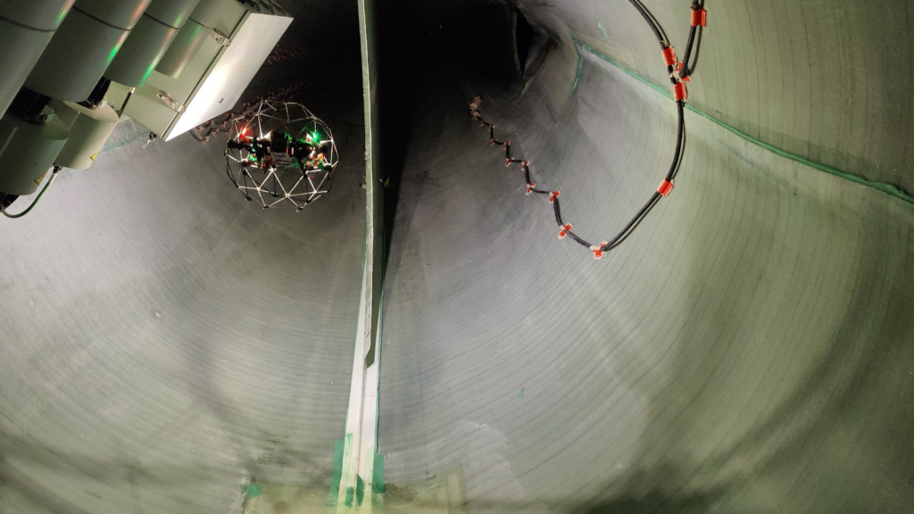
Introduction End of Warranty (EoW) campaigns mark a crucial phase in the operational life cycle of wind turbines. These campaigns involve thorough inspections of major components, rectifying any defects to ensure that the turbine is handed over to the owner without significant damages. In this article, we will delve into the best recommended practices for planning and executing EoW campaigns, with a specific focus on wind turbine blades. Strategic Planning for EoW Campaign The planning for an End of Warranty campaign begins during the development phase, involving agreements on the warranty period after taking over the blades. Manufacturers may offer warranties ranging from 2 to 5 years. Planning is critical, with the inspection campaign ideally scheduled as late as possible within the warranty period. This allows for the development of more defects while still ensuring ample time for inspections and data analysis. Factors to Consider in Planning Lightning-Dense Areas: Schedule inspections during high lightning activity months to test the efficiency of the lightning protection system and address potential issues under warranty. Icing Potential Areas: Plan inspections after the second winter to test the de-icing/anti-icing system under operational conditions. This timing ensures coverage for potential damages caused by ice accumulation. Rain Event Seasonality: Observe as many rain events as possible before EoW inspections to analyze erosion development rates and assess the performance of the leading edge protection. Inspection Scope External Inspections External inspections provide a baseline for surface conditions, leading edge protection performance, erosion development rates, and detection of structural damages in the outer laminate layers. This includes assessing the lightning protection system, potential lightning attachments, and the condition of receptors and add-ons. Internal Inspections Internal inspections are equally important, detecting manufacturing nonconformities such as wrinkles and defects in adhesive bondlines. They also reveal early-life fatigue damages, including major cracks and delamination in inner laminate layers. Analysis and Maintenance Actions Once inspection data is collected, a thorough analysis is conducted to determine the most relevant maintenance actions for each damage. While the common approach is to repair defects during an EoW repair campaign, some defects may warrant a long-term maintenance plan between the owner and the manufacturer. Wind Power LAB can assist in producing claim documents defining the best recommended actions for each defect group, facilitating a smooth transition in the end of warranty claim documentation package. Conclusion End of Warranty campaigns are pivotal for ensuring the longevity and optimal performance of wind turbines. Strategic planning, comprehensive inspections, and informed maintenance actions are key elements in maximizing the benefits of these campaigns. For further insights and detailed discussions on EoW campaigns, reach out to our blade specialists at Wind Power LAB. Don’t be a stranger Feel free to contact us by clicking here
Wind Turbine Blade Surface Defects
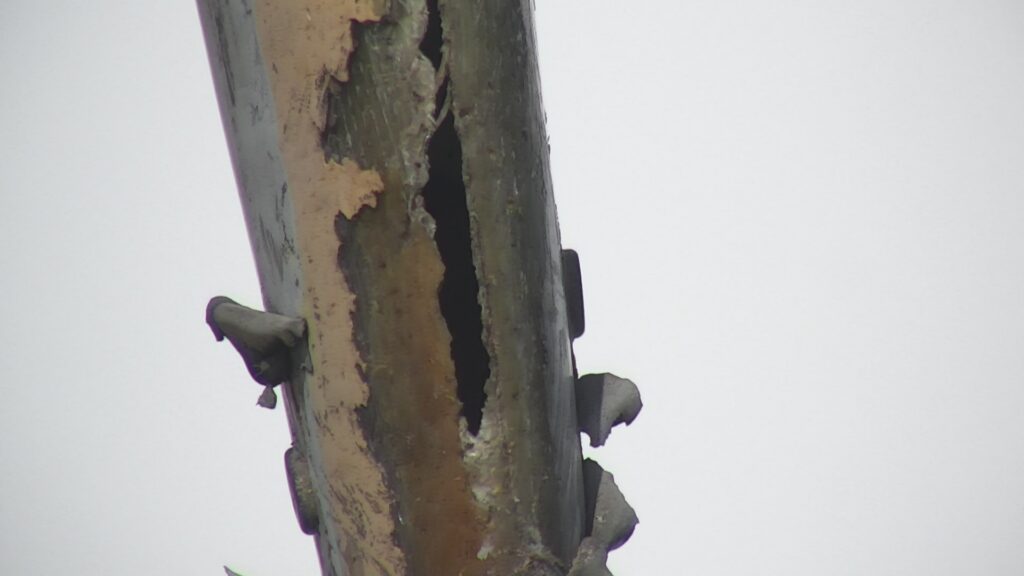
The surface of the wind turbine blades is designed to withstand the relentless forces of nature, exposed to a barrage of elements: wind, rain, hail etc. In this blog post we will dig more into some of the wind turbine blade surface defects that are observed in the industry. Some progress has been made in describing the different defect types. In this article we present our categorization, how these surface related defects are defined, and the distinguishing characteristics of each type. Voids Void is a generic name for pinholes, air inclusions and air pockets in the surface coat. The cause of occurrence for pinholes and other void types are different. However, all voids are related to flaws during the coating process at the factory or during onsite repairs. Voids in paint are caused by imperfections and contamination in the surface during final coating. Voids in filler and surface mat are caused by air inclusions in the filler or top layer Epoxy. Voids weaken the surrounding surface coat, enabling other surface defects or erosion to develop. Voids do not have an impact on the blade integrity, but in erosion zones the presence of voids accelerate the development of erosion. Defect indicators: Voids in paint appear as pinholes in the surface, ranging from 1-4mm^2 Voids in the filler and surface mat appear as sharp-edged slots in the blade surface, ranging from 5-1000mm^2 Appear as single defect or in clusters Interchangeable defects: Chipping, rough edges around defect. Peeling, larger area of missing coating in the same layer. Erosion, continuous strip of missing surface coat in different layers on the outer 1/3 of LE. WLA, Burn-mark or contamination around defect. Chipping Chipping is a secondary defect; it only occurs after another surface defect has created a breach in the surface coat that chipping can develop from. Chipping is the consequence of sand, rain, hail and other particles impacting on an exposed surface coating. On a healthy surface coat, these impacts would have neglectable effect on the coating as they would rebound. But due to an opening caused by other defects the particles can impact directly on the coating layers. Chipping mainly affects brittle materials and is therefore limited in development to the surface laminate. Due to its limitation, chipping does not have an impact on the blade integrity. In the LE erosion zone chipping can lead to accelerated erosion. Defect indicators: Rough and uneven edges around the defect border. Varying depths of the defects showing different surface layers Interchangeable defects: Voids, sharp defined edges around defect Peeling, larger area of missing coating in the same layer Erosion, continuous strip of Peeling Peeling is caused by poor adhesion between layers in the surface coat. The adhesion loss is due to either contaminated surface, insufficient grinding of substrate, fault in coating mix or material batch. In severe cases peeling can leave several m^2 exposed to erosion and other weather effects. The defect itself has little impact on the integrity. But the exposure of underlying substrate can lead to accelerated development of other defects. Defect indicators: Rough and uneven edges around the defect border. Varying depths of the defects showing different surface layers Interchangeable defects: Voids, sharp defined edges around defect Peeling, larger area of missing coating in the same layer Erosion, continuous strip of missing surface coat in different layers Want to learn more? In this blog, we have delved deeper into the various types of defects and damages found on wind turbine blade surfaces. We have explored their definitions, the processes through which they develop, and their interchangeable characteristics. If you’re eager to broaden your knowledge on wind turbine blade surface defects and damages, we offer specialized blade training programs designed to enhance your expertise in blade-related technologies. Our training covers topics like blade-related defects, lightning protection systems (LPS), and the fundamental principles of blade construction, providing you with a comprehensive understanding of these crucial aspects.. Click here to learn more
The Sky’s The Limit – Why Wind Turbines Blades Are Becoming Longer and Longer
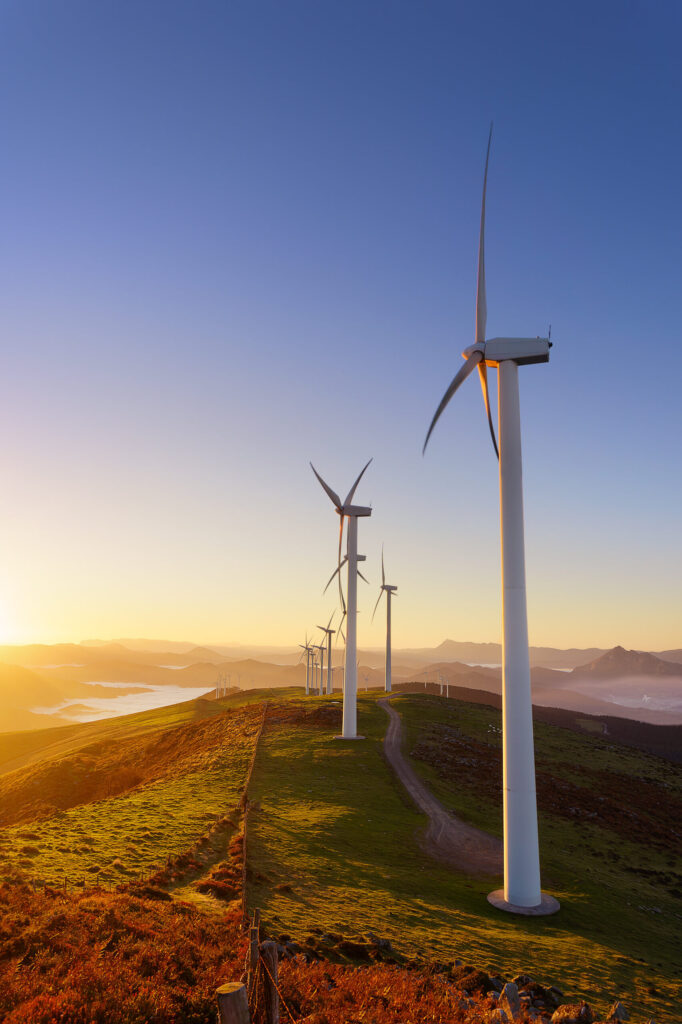
The Sky’s the Limit: Why Wind Turbine Rotor Diameters Keep Growing The clean energy revolution is sweeping the globe, and at the heart of it is the ever-expanding world of wind energy. Wind turbines have come a long way since their inception, and one noticeable trend is the increasing size of their rotor diameters. But why are wind turbine manufacturers constantly striving to build bigger and bigger rotors? In this blog post, we’ll explore the key factors driving this trend and the benefits it brings to the renewable energy industry. Maximizing Energy Capture One of the primary motivations behind the enlargement of rotor diameters is the desire to capture more energy from the wind. Larger rotor blades cover a greater swept area, allowing turbines to capture more wind energy, even in lower wind speeds. This improved energy capture leads to higher electricity production, making wind farms more efficient and economically viable. Reducing Cost of Energy As rotor diameters increase, the cost of energy production decreases. This is because larger rotors generate more power without significantly increasing the cost of other turbine components like the tower or generator. This results in a lower levelized cost of electricity (LCOE). Lowering Wind Turbine Costs Larger rotors enable wind turbines to operate at lower wind speeds effectively. This means that they can be located in regions with less consistent wind resources, which significantly expands the number of suitable sites for wind farms. This diversification of location options helps reduce transmission costs and grid congestion, making the deployment of wind energy even more cost-effective. Scaling Up Wind Turbine Technology Advancements in materials science and manufacturing techniques have made it possible to build increasingly larger rotor blades. Composite materials like carbon fiber are both lightweight and durable, enabling the construction of massive blades that can withstand the stresses of wind turbine operation. Additionally, improvements in aerodynamic design and control systems have made it feasible to operate these larger turbines safely and efficiently. Maximizing Wind Energy Potential Wind turbine rotor diameter growth aligns with the goal of tapping into higher-altitude winds. The wind at greater heights tends to be more consistent and stronger, providing an opportunity for increased energy production. This trend also supports the expansion of offshore wind farms, where larger rotors can harness the more powerful winds over open waters. Technological Challenges While the push for bigger rotor diameters is promising, it’s not without its challenges. Manufacturing, transportation, and installation of massive blades require innovative solutions and investment in infrastructure. Additionally, the stress on the grid caused by the intermittent nature of wind energy generation must be addressed through grid improvements and energy storage solutions. Want To Learn More? Don’t be a stranger – Feel free to reach out by clicking here
Rain Erosion Testing’s NEW Analysis Methodology

Rain Erosion Testing (RET) is an integral part of Leading Edge Protection (LEP) development and certification. It measures the durability of materials to rain droplet impacts. There are different methods to perform RET, including jet impacted stationary samples, solid projectile impact tester, and utilizing a whirling arm tester. In this short article, the main focus will be whirling arm testing. The method consists of one or test specimens mounted on a rotating arm spinning at high velocities. The rotating specimens are exposed to a controlled rain field generated by the testing machine, where rain intensity and droplet size can be controlled. The damage progression is recorded through image acquisition over the complete duration of the test. The image material is then assessed by a specialist to identify the different stages and locations of defects. Finally, the data is visualised in a V-N curve, where V is impact velocity and N is the number of specific impacts. Another common resultant representation of a RET is the incubation period, defined as the time until first damage is observed on the testing sample. There are 3 main failure modes observed during RET testing of LEP products. The first one is uniform erosion and is typical for older coatings. This defect type is characterised by gradual LEP material removal from the high-speed end towards the low-speed end of the testing sample. The second defect development mode is adhesive failure, where the interface between the LEP and the substrate fails due to insufficient adhesive strength. The third commonly seen defect type is local failure around a pre-existing imperfection from manufacturing. This is often the damage mechanism visible on newer LEPs, which are stronger and have improved adhesion to the substrate. Due to the durability of modern LEP products, the amount of water impacts required to cause failure is significant. This leads to either very high rotation speed of the samples, or very long testing times to achieve meaningful testing results. If the rotation speed during RET is too high, it can lead to unrealistic defect modes or test results. This is mainly due to breaking of the droplets to smaller sizes, or vaporisation. On the other hand, longer tests are more expensive and create more data for analysis. Wind Power LAB, in collaboration with R&D Test Systems and DTU – Technical University of Denmark, has developed an enhanced bespoke method for assessment of RET image data collected during testing. In the first stage of the project, which is now completed, we developed an annotation tool that enhances the process for the specialist looking at test images. In the next stage of the project, we will utilise computer vision and machine learning to automatically detect defects/damages on the test imagery. Our initial trials have shown significant potential for the success of such endeavor. Stay tuned for more details on the testing solution software as it develops. It is believed that through this innovation project, Leading Edge Protection coatings and other materials bound for Erosion Testing can be more efficiently and dutifully assessed. In turn, reducing the time to market through productive methodical research and development processes. Hristo Shkalov, Senior Blade Specialist – Wind Power LAB If you are interested in more blog post click here
Leading edge protection – The basics
Leading Edge Protection – Is it Needed? Leading Edge Protection (LEP) is essential for wind turbines with nominal power larger than 2MW. Due to the increased blade length, the tip speed of these turbines can reach up to 90 m/s. That means for sites with annual accumulated precipitation of 0.7 m, the tip area of the blade is hit by an accumulated water column of approximately 10.5 m per year. The introduction of 90+ m diameter rotors coincided with the development of the first large utility scale windfarms in the early 2000s. The combination of high tip speeds and installations in harsher offshore and onshore environments also caused tremendous erosion problems. Older blades have been produced without factory applied LEP and frequently require large repair campaigns of LE damages. With the industry recognizing erosion as a major issue, the race for developing an effective erosion protection solution started. Newer blade generations are now produced with a factory installed LEP in the erosion zone. However, these solutions are not flawless, and repairs are required throughout the lifetime of the turbine. What and Why? To ensure that the most optimal repair/retrofit method is selected, the wind turbine operator should understand the observed damage mechanisms on their site. In the aggressive erosion zone, usually spanning a few meters starting from the tip, the loss of material is driven by environmental conditions. When rain hits the blade surface, a combination from the stress waves propagation, surface fatigue from the repeated droplets impact and the direct deformation at high impact speeds are considered the main reasons for erosion development. In that area, the defect is observed as a continuous stripe of material loss, usually centred around the LE. Outside of the aggressive erosion area, surface defects on the LE develop around pre-existing imperfections in the LEP or the underlying layers. The defects there are characterized by variety in sizes and discontinuity, more uneven depth, random location, and rough edges. The general recommendation for LEP repair is heavy duty solution in the aggressive erosion zone and easy to apply solution for the remaining LE erosion zone. There are 3 main leading edge protection groups – coatings, tapes, and shells. Each of them has its pros and cons, so a good understanding of the erosion condition on a specific site is vital to select the most suitable LEP. LEP Solution Overviews LEP shells are precast with a specific shape for each blade type. They are installed on the blade with an adhesive and the edges are sealed with a sealant to prevent water ingress. This LEP type has the highest level of erosion protection. On the other hand, due to its thickness and shape, it affects the AEP negatively. The solution is suitable for the aggressive erosion zone of wind turbines in harsh environments in their early to mid lifetime. Defects that can be observed on the LEP shells are peeling at edges and overlap zone and delamination at the adhesive interface. LEP tape is supplied in rolls. The adhesive is pre-applied on the LEP tape, however, adhesion promoters and application solutions are required during installation. Edge sealant shall also be applied to protect the edges from water ingress. This solution provides solid erosion resistance, however, it degrades under the effect of UV radiation. It is relatively hard to apply especially around the tip, due to the change of shape there. Moreover, contamination and imperfections in the underlying surface might cause failure of the LEP tape adhesion. Defects on this LEP type include chipping, peeling and scratches from impacts with sharp external objects. LEP coating is characterised by higher elasticity and flexibility than the normal paint applied on the other areas of the blade. The solution is suitable for combination with LEP shells, covering the erosion area outside the aggressive zone. The application process requires a well executed surface preparation. Insufficient sanding or contamination would greatly impact the adhesion quality of the erosion resistance. Another defect enabler for the LEP paint is the propagation and interaction of the compressional waves from the raindrop impact, which can cause delamination in the interface of the LEP and the underlying surface, or between two layers of LEP coating if the solution is not single layer. Conclusion Leading Edge Protection is a critical component to protect the longevity of wind turbine blades. Without proper care and maintenance, cosmetic issues on the leading edge of wind turbine blades can turn into production robbing problems and eventually structural damages that may cause catastrophic failures. If you are unsure of the status of your blades, options in the market, or need guidance about leading edge protection – reach out to an expert! Hristo Shkalov, Senior Blade Specialist – Wind Power LAB Interested in other blog topics. Click here