
Replace or Repair? – Exploring Wind Turbine Blade Failures
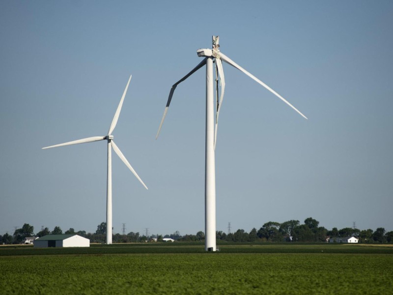
Critical blade defects leading to failure of blades can be caused by excessive force or fatigue damage. This poses a significant risk and creates extreme economic impact for a wind turbine owner. Therefore, it is important to ensure wind turbine blades (WTBs) last their full designed lifetime. Blades can fail via different types of failure modes. This is highly dependent on the individual blade design as selected by the Original Equipment Manufacturer (OEM). Failures can be related to design, manufacturing defects, environmental factors, lightning strikes, external impacts, and fatigue. These damages will lead to complex blade repairs or full blade replacements. To understand if a blade should be repaired or replaced, first the blade must be investigated after a structural damage is detected. In a Root Cause Analysis (RCA) investigation, different initial hypotheses are enlisted if failure is related to design, manufacturing, fatigue, or control issues. Therefore, the blade design type, the location of the failure, defect characteristics and SCADA data should be investigated thoroughly to proximate the cause. Initially, the structural damage in the final failure should be categorized if it is a: · Potential initiator of the failure: Key evidence to point out that the potential initiator damages are the defined patterns of cracks, delamination surrounding the damage, and stress whitening of laminate. · Damages caused by the damage initiator: The damage initiator can cause effect on its neighboring structures. This has an undefined crack pattern and shows more of a laminate tear appearance which occurs during collapse. Once damages are categorized, more in-depth investigation will be applied to the potential initiator of the failure if it is associated to manufacturing, fatigue or irregular loading caused by faulty control systems. Therefore, it is of importance to build a failure scenario supported by facts, carry out a proper investigation which highlights the failure mechanism, and understand how it has progressed leading to the final failure. To restore the blade structural integrity, the repair must consider the following: · Damage severity level: specification of how much the damage has affected the blade in terms of material damage and extension of area affected, i.e., how big, and deep the damage is. · Damaged region: correlated to severity level but, it is important to understand that blades are composed of different structural components. If these structural regions are affected, then severity level becomes higher. · Aerofoil geometry requirements: since blades are designed with complex geometry, ensuring that aerodynamic efficiency is reached to cultivate maximum power from the wind resource. If the blade’s structural components are affected, and if the damage extension is too big and deep, then a repair is less likely to be successful. It is important to highlight that when a repair is performed, it must restore the blade’s structural integrity and should endure loads during the blade’s remaining lifetime. Taking these considerations into account, a repair scope can be built where other factors are accounted for, including material and tools requirement, labour, logistics and weather. These factors will be the base of the cost of the repair. That is why it is highly suggested that a repair cost breakdown must be requested, to mitigate the cost of repair in comparison to the cost of blade replacement scenario. When deciding if a repair of a blade is feasible, it is important to determine the affected areas of the blade. If the damage is confined to the blade shells, it is in most cases possible to repair the blade. The main driver of repair time and complexity is determined by the area the defect covers. If the defect is located at the blade beam, root, and web structure, it affects load carrying parts of the blade. This increases the complexity and size of a repair significantly, as the overlap between laminate layers in the repair ensures that the repair can handle the loads in the structural parts of the blade. To determine if a repair exceeds the value of the blade, it is necessary to establish the position of the blade damage, effect on the blade structure and size of the repair. Then, repair time and cost are estimated and matched against cost of a blade replacement. If a replacement has been determined as the best course of action, then it is essential to find matching blade(s) that balance with the remaining blades on the turbine. Turbine blade manufacturing is still to a larger degree a handcraft, it is therefore common to encounter discrepancies between blades of the same type. This is due to the manufacturing process, where the glass fiber layers are impregnated with epoxy resin. It is common to see difference in saturation levels of composite laminates, and resin pools in the blades are also an expected occurrence during the manufacturing process. This creates variation in blade weight and load distribution across the blade span. Therefore, it is a good indication that if two blades match in weight but, the blade center of gravity (CoG) and loads at the blade root, also known as root bending moment (RbM), need to match for the blade set to balance. If a selected blade does not fit to the other blades in the set, it will cause rotor imbalance that causes unwarranted loads to the blades, bearings, and the drivetrain. It is possible to adjust some discrepancy in the blade attributes using weight blocks or ballast boxes inside the blade. These weights are often placed at the midspan of the blade. There is a limitation to the amount of weight that is possible to add, as it increases loads locally in the weight position. This can cause early life fatigue if the loads exceed the allowed threshold. It is therefore true that not all blades are possible to matched if their weight, CoG or RbM is exceeding the adjustment range of the blade set. Authors – Wind Power LAB Morten E. Handberg, Chief Blade Specialist at Wind Power LAB https://www.linkedin.com/in/morten-handberg-24196b11/ Aura Vanessa Guzmann, Senior Blade Specialist at Wind Power LAB https://www.linkedin.com/in/aura-venessa-paguagan/
Lightning Protection System
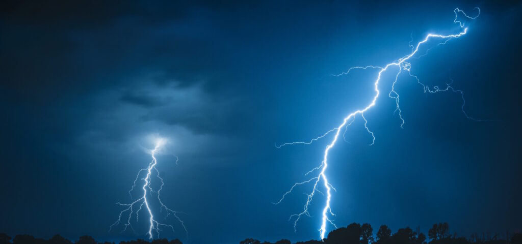
By Morten Handberg, Chief Blade Officer at Wind Power Lab; and Nick Baker, Associate Director at Global Risk Solutions. Lightning damages to wind turbine blades account for a significant percentage of operational onshore wind claims. Based on more than 3,500 renewable losses, GRS’ loss database indicates that lightning damage accounts for 60% of operational blade losses and almost 20% of operational wind losses overall. In our experience, we have found that the levels of damage observed can be highly variable – from repairable ‘puncture’ like damage, to the blade’s destruction. This white paper focuses on the blades’ lightning protection system (LPS). This white paper focuses on the blades’ lightning protection system (LPS). We are often asked how these systems work and why severe blade damage can still occur. Here we will give an overview of how a typical LPS works and provide our best practice recommendations. LPS description The LPS is a passive lightning protection system, ensuring that lightning strikes hitting the blade is transferred to the grounding. The systems are tested in accordance with the IEC 61400-24 standard. Dependent on the test tier, the system is designed to handle 100-200kA, without significant system wear. The diagram below shows a typical LPS: LPS Components Receptors. The receptor is a component made from metal, either copper or equivalent current transferring metal alloy. It is designed to attract lightning and transfer the load to the receptor block. The receptor is a replaceable component that is mounted post blade production. Risks of failure are worn receptor base or missing connection to the receptor block. Visual inspection can be used to determine a receptor’s condition. Receptor Block. To connect the receptor with the down conductor cable, an aluminium block is cast into the blade with the down-conductor during blade production. A replacement requires a complex laminate repair as the blade laminate must be removed before the block can be accessed. Common issues involve detachment or missing connection to down conductor cable or receptor. A visual inspection cannot detect a lost connection between the receptor block and down conductor cable. Instead, it can be checked with a resistance measurement. Down conductor cable. The design of the cable varies between the different OEM’s, including copper mesh, solid copper cable, linked aluminium plates and solid cable. The cable is centered on the web of the blade. It can be located on both LE or TE side dependent on the OEM design. Repair is possible but complex. Failure types include missing connection to root terminal, or receptor block and cable separation due to fatigue. connection to the root terminal can be checked with an internal visual inspection, which can be performed without entering the blade. Detecting separation of the down conductor cable is possible with a dedicated internal inspection. Root connection. The root connection is designed to transfer the load from the cable to the bypass system. Failure modes at the root terminal include missing connection, which is not designed to carry electrical current. Lightning transfer system. The design of the transfer system varies between the different OEMs. It can be spring coupling, brushing, or spark gap. These systems are designed to receive limited wear from lightning transfer; thus, they occasionally need replacement. A defect that can be observed in the lightning transfer system is insufficient contact in the case of the brush or coupling, or too large distance in the case of the spark gap. Visual inspection can detect such defect; moreover, for brush and coupling designs a resistance measurement can be performed. Our LPS Recommendations Operators can reduce the risk of lightning damages by conducting regular scheduled LPS inspections. A maintenance strategy must be in place to define scope and inspection frequency. Receptor wear and sealant damages can be observed during a standard external inspection; down conductor connection to the root terminal can be visually inspected during planned turbine maintenance; the integrity of the down conductor can be examined during an internal blade inspection. During an LPS inspection, it is important to: Check the surface condition of the receptor. If material wear exceeds below the blade surface, a replacement is required. Check that the connection between the down conductor, root terminal and lightning transfer system is intact. If scorching and/or arching is detected near the root terminal, the connection is likely missing or par7al. Check the surface condition of the transfer system. Too large spark gap or poor connection conditions could cause undesired lightning jumps to other parts of the turbine. Major failures due to a lightning strike to the blade can be divided into two main categories: A “force majeure” event is described as lightning with an unusually high current that exceeds the design limitations of the LPS. A defect in the LPS leads to a reduced ability to transfer the lightning or a missing connection, thus reducing the likelihood of lightning traveling through it safely to the ground. The risk of the la]er can be reduced by having a maintenance schedule in place for blades. This would also prevent some fatigue damages from going unnoticed. While the “force majeure” damages are hard to influence, defects due to malfunctioning LPS can be minimised with a more focused effort from the industry. At present, Germany is the only country with meaningful legislation about the inspection of an LPS – it should be inspected every four years as a minimum. For comparison, turbine owners in Denmark are only obliged to inspect the LPS of their turbines when they have reached 20 years in operation. Installing lightning trackers on sites can help to collect more parameters for lightning that are hitting the turbines. The wind industry will benefit from having easy access to accurate lightning data from the local site when assessing damage from lightning strikes. Ultimately, from an insurance perspective, the breadth of cover commonly offered by a typical onshore wind policy regarding defects coupled with the difficulty in determining the strength of a lightning strike can make it challenging to apply any adjustments to the claim. However, the
Can You Control Lightning Risk?
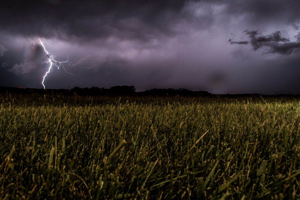
Harnessing wind energy is a remarkable stride towards sustainability, but it’s not without challenges. Wind turbine blades, reaching for the skies, face the potent force of lightning. These strikes can compromise blade integrity, affecting efficiency and safety. Innovative solutions are key – from integrating conductive materials to advanced lightning detection systems. This is where Wind Power LAB’s lightning surveillance service, LASSIE, steps in. By leveraging cutting-edge technology, LASSIE provides real-time monitoring of atmospheric conditions, offering crucial insights to operators. With lightning’s unpredictable nature, LASSIE empowers wind farms to make informed decisions, saving cost in operations after storms and minimising the risk of lightning-related damages propagating. By combining the might of wind energy with intelligent monitoring, we not only ensure uninterrupted power generation but also safeguard wind farm operation against the elemental fury of lightning. Together, we’re writing a sustainable energy future. Want to get your wind farm under surveillance? It is easily done with Wind Power LAB’s LASSIE. Click here to learn more about our lightning surveillance service or sign up for a free trial here. #RenewableEnergy #WindPower #Innovation #Sustainability #LASSIE
Why is QC of wind turbine blades important?
Introduction Wind turbine blades play a crucial role in the success of wind farm projects, and their quality directly impacts performance, safety, and long-term cost-effectiveness. As wind farm developers invest significantly in these blades, it becomes essential to ensure that they meet the quality standards before leaving the factory. This blog post explores why quality control (QC) of wind turbine blades leaving the factory is of utmost importance. Protecting Investments and Reducing Costs Wind turbine blades constitute a substantial portion of the total turbine cost, making them a significant investment for wind farm developers. Imperfections in production are inevitable with large composite structures. While some imperfections may fall within acceptable tolerances, others require repairs. Conducting QC checks at the factory stage helps identify any defects or weaknesses in the blades early on, allowing for timely repairs and minimizing the risk of expensive post-installation repairs. By addressing issues before blades leave the factory, developers can protect their investments and reduce the multiplied cost associated with fixing defects after installation. Ensuring Blade Integrity and Performance When the QC is solely conducted without the presence of a client representative, there is no second opinion on the magnitude of the defects. By implementing additional QC measures, such as reviewing the original equipment manufacturers (OEM) QC documentation and performing external and internal inspections of blades by experienced specialists, developers can establish a baseline for the blade’s integrity. This enables them to determine if any defects are due to wear and tear, force majeure, or inherent to the production process. By ensuring blade integrity, developers can maximize performance and extend the operational life of wind turbines. Enhancing Safety and Reducing Risks Safety is paramount in the wind energy industry, and flaws or weaknesses in wind turbine blades can lead to structural failures, compromising the safety of personnel and nearby communities. By proactively addressing blade defects before installation, developers contribute to a safer working environment and reduce the likelihood of accidents or turbine failures. Quality Assurance and Reputation Implementing comprehensive QC measures for wind turbine blades leaving the factory demonstrates an active interest in the blades’ condition. This not only raises the overall quality of work from the factory but also helps wind farm developers build a reputation for delivering high-quality projects. By showcasing a commitment to ensuring the integrity and performance of wind turbine blades, developers can enhance customer satisfaction, build trust, and differentiate themselves in a competitive market. Insurance Benefits Having control over the quality of wind turbine assets can lead to better insurance deals. By demonstrating a proactive approach to QC and providing comprehensive documentation of the blades’ condition, developers can showcase their commitment to risk management. Insurers are more likely to offer favorable terms and premiums to projects where asset quality and control are evident. This translates into significant cost savings over the project’s lifespan. Conclusion Quality control of wind turbine blades leaving the factory is vital for wind farm developers. By conducting thorough QC inspections and implementing additional measures such as independent reviews, inspections, and documentation, developers can protect their investments, ensure blade integrity, enhance safety, maintain a reputable image, and gain insurance benefits. The proactive approach to QC demonstrates a commitment to delivering high-quality projects and reinforces the long-term success of wind farm developments. Want To Learn More? Don’t be a stranger – Feel free to reach out by clicking here
Wind Turbines & Lightning Strikes
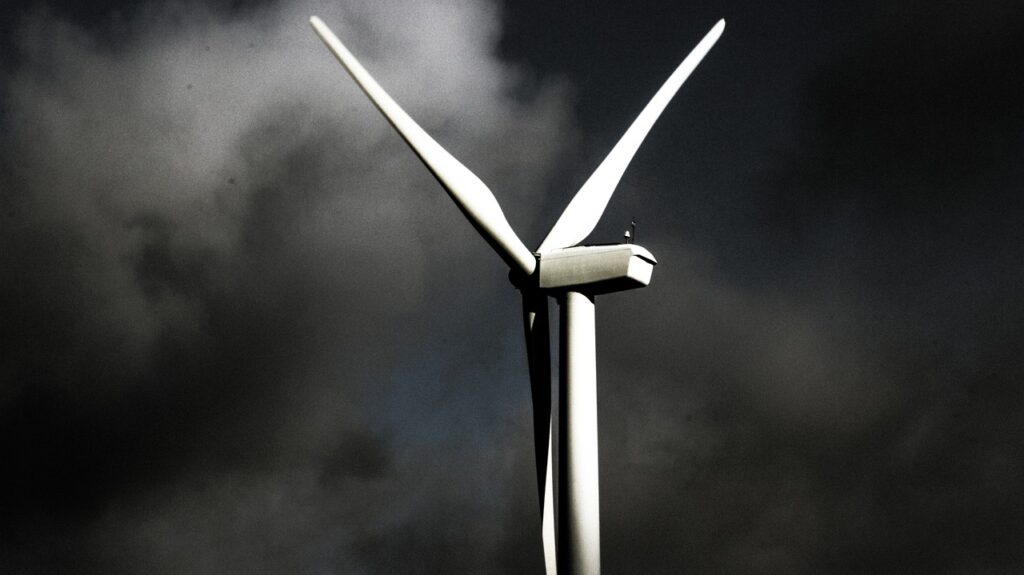
By Ed Hillier, Associate Director, Natural Resources, Charles Taylor Adjusting with Inputs from Morten Handberg, Chief Blade Specialist, Wind Power LAB Lightning is an ever-present natural phenomenon. Indeed the destructive power of a lightning strike, and the resulting wildfires it can cause, is actually key to the lifecycle of some species of flora. However, the increased use of composite materials in aviation in the last half century has led to a renewed interest in this topic as increasing numbers of structural aircraft components are composite in nature which can potentially be more susceptible to damage from lightning strikes. On this basis, sophisticated lightning protection systems incorporating numerous materials are now a key safety feature in all aircrafts. In short this is a well-researched and understood science within the aviation industry. Conversely the insurance market has experienced considerable losses as a result of damage caused by lightning strikes to Wind Turbine Generators (WTG), especially damage to the blades. Unattributed comments by the Royal Canadian Airforce suggests that a commercial aircraft is struck by lightning approximately every 1,000 to 3,000 flying hours although there is often little damage, if any. Why should this be so? The first point to consider is the construction of a WTG blade which is essentially Fibre-Reinforced Plastic (FRP) shaped to form the desired aerofoil shape. The former material (fibres) is an electrical insulator whilst the bonding resins are an electrical conductor although when amalgamated to form a blade the structure is a less effective conductor than a comparable unit made from aluminium or carbon fibre. This is a major difference to aircraft which are in general excellent conductors of electricity as a result of their high aluminium content meaning that the free-flowing current has to be channelled to a dissipation point: typically trailing edges of control surfaces. Conversely WTG blades need to have specific metallic components engineered into them for the express purpose of creating a conductive medium as part of a path to earth. Returning to WTGs, the net result is that despite being relatively unattractive as an electrical conductor, their blades are still struck on a regular basis due to their elevation and the relative lack of taller, more conductive structures in the vicinity. If there was no Lightning Protection System (LPS) built into these blades, they would be unable to quickly dissipate the huge and sudden energy release which would likely result in catastrophic damage. In order to overcome this, a WTG is fitted with a series of components that comprise the LPS which are typically as follows: • Blade receptors • Down conductor • Earth termination point In a recent study1 it was identified that 90% of all blade damage occurs in the first four metres of the blade travelling from the tip toward the root. In order to mitigate this, the most popular LPS system design integrates a tip receptor and a number of metal receptors along the length of the blade that are connected to a down connector. However, it is also important to recognise that the blade area is much larger than the area of the receptors, but WTG manufacturers have traditionally weighed this up against the statistical likelihood of a damaging strike. Whilst all commercial LPS are designed around the standards as set out in IEC 61400-24 which was first published in 2002, an updated 2018 version addresses the lightning risk of the increasing size of WTGs and their associated technology. That said, from anecdotal claims information there would appear to be an increase in damaging lightning strikes to blades which would indicate that the progress in LPS development is not always in line with the development of increasingly larger WTGs. This is something that the 2018 edition of IEC 61400-24 seeks to rectify. Given the increasing number of deployed WTG especially in the onshore market, that were designed before these new standards were adopted, the commercial reality of the cost of retrofitting these fleets versus their remaining operational life and income is a challenge many operators may need to consider in the coming years. So where does this leave the Insurer who is facing an increasing number of lightning related losses and a correspondingly disappointing loss ratio? The answer to this in terms of onshore WTG may not be a palatable one but will centre largely on the nature of the WTG generating assets they insure, their operational life, and the willingness or otherwise of the Insured to invest in preventative measures. That said, there is only so much that can realistically be done to improve the LPS of an existing asset and so perhaps prudent risk selection and policy wordings can assist with a more equitable risk transfer. In contrast, in the offshore space where the majority of the technological advances are being made and the majority of larger capacity WTG units exist, damaging lightning strikes rarely seem to occur. In summary, lightning has, is, and always will be a natural phenomenon that humanity and its engineers can best hope to mitigate rather than tame. Through increased knowledge will come resilience. In the meantime, insurers will be called upon to fill this gap with suitable risk transfer products and by working with all interested parties, a better-quality risk will result. 1 Garolera, A.C.; Madsen, S.F.; Nissim, M.; Myers, J.D.; Holboell, J. Lightning Damage to Wind Turbine Blades From Wind Farms in the U.S. IEEE Trans. Power Deliv. 2016, 31, 1043–1049
LIGHTNING PROTECTION SYSTEM (LPS)
The Lightning Protection System (LPS) is a passive lightning protection, ensuring that lightning strikes hitting the blade are transferred to the grounding. The systems are tested in accordance to the IEC 61400-24 standard. Dependent on the test tier the system is designed to handle 100-200kA, without significant system wear. Receptors The receptor is a component made from metal like copper or equivalent current transferring metal alloy. It is designed to attract lightning and transfer the load to the receptor block. The receptor has a conic screw below the base that ensures contact to the receptor block. The receptor is a replaceable component that is mounted post blade production. On older blades the tip receptor can be a massive copper piece taking up the outer 20cm of the blade tip. Risks of failure are worn receptor base or missing connection to the receptor block. The wear mechanisms include arching of the receptor base from lightning attachments and corrosion from water ingress between the receptor and receptor block. Visual inspection can be used to determine the condition of a receptor. Scorching and deformation are the most common signs of wear from lightning on the receptor base. Lightnings will also remove some material of the receptor base over time. If material removal proceeds below the blade surface, the receptor will have a reduced attractiveness to lightning. Missing sealant allows water ingress between the receptor and the receptor block, which can cause corrosion and damage to receptor block over time. Lightning Protection system receptor block To connect the receptor with the down conductor cable, an aluminum block is cast into the blade with the down-conductor during blade production. Replacement requires a complex laminate repair as the blade laminate must be removed before the block can be accessed. During post processing of the blade the receptor hole is drilled along with the thread for the conic screw. Risk of failure is detachment or missing connection to down conductor cable or receptor. Missing connection to the receptor can be deducted from damaged or missing sealant around the receptor and corrosion of the two components. Another cause for imperfect connection between the block and the receptor is if the receptor has been screwed at an angle to the block, causing only partial contact, thus reduced capacity to safely transfer lightning. A missing connection between the receptor block and down conductor cable cannot be detected by a visual inspection. Instead, it can be checked with a resistance measurement. This type of check is recommended only as investigation to locate defect in a malfunctioning system and not as part of general inspection. Down conductor cable The design of the cable varies between the different OEM’s, including copper mesh, solid copper cable, linked aluminum plates and solid cable. The cable is centered on the web of the blade, it can be located on both LE or TE side dependent on the OEM design. The cable is cast into the blade during production. Repair is possible but very complex and due to a clamping device changing shape of the cable the blade has additional risks of wrong lightning attachments post repair. If any carbon is used in the blade to increase the structural strength, it is important that the carbon is included in the LPS to avoid high difference in electric potential between the cable and the carbon laminate. If the carbon is not included, it must be thoroughly checked that it does not provide a risk of lightning jumping internally in the blade. Failure types include missing connection to root terminal, or receptor block and cable separation due to fatigue. Connection to the root terminal can be checked with an internal visual inspection, which can be performed without entering the blade. Detecting separation of the down conductor cable is possible with a dedicated internal inspection. A skilled technician or internal drone can reach 1/3 into the blade, while a sewer crawler can inspect until a few meters from the tip. The most detailed inspection is achieved by a technician or drone inspection. Root connection The root connection is designed to transfer the load from the cable to the bypass system. Blades are equipped with a slipring close to the root. The down conductor cable is connected to the slipring via a connection bolt through the blade laminate or via the backplate. Failure modes at the root terminal include missing connection to the down conductor cable. If no connection is established lightning would seek other paths to the ground, risking damage to the laminate or drivetrain, which is not designed to carry electrical current. Lightning transfer system The design of the transfer system varies between the different OEMs. It can be spring coupling, brushing, or spark gap. The brush and coupling designs are made to have as minimum partial contact from blade to grounding system at all times during operation. These systems are designed to receive limited wear from lightning transfer. The spark gap will transfer the load through an arch between the slipring and the lightning rod. Thus, significant wear could be expected, leading to an occasional need of replacement. The defect mode that can be observed in the lightning transfer system is insufficient contact in the case of the brush or coupling, or too large distance in the case of the spark gap. In both ways the result would be a less effective, or completely dysfunctional LPS. Visual inspection can detect such defects, moreover for brush and coupling designs a resistance measurement can be performed, if there are doubts for the functionality of the system. Lightning Protection System measurement The currently used method of determining whether an LPS is functional is by conducting a resistance measurement. It is performed by connecting multi-meter probes to the two ends of an LPS, essentially creating a closed circuit. To check the functionality of the system within a blade, you must connect one probe to the tip receptor and one probe to the root connection. To check the functionality on turbine level, you must connect one
Lightning Has Struck – What happened?
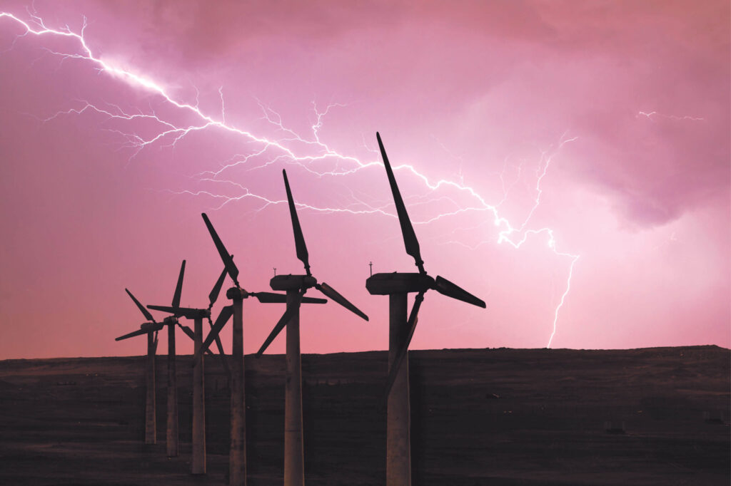
Lightning has struck – so what happened and how can it be mitigated? Lightning attaching to a turbine will always find its way to the ground. The current will usually find the path with the least resistance, which in the case of a wind turbine is through the Lighting Protection System (LPS) of the blade, to the hub and then through the tower to the ground. In this scenario, the blade and turbine will not endure any damage and normal operation can continue. However, as Wind Power LAB observes in the industry, in some cases of lightning, the LPS fails to attract the strike and the current needs to find an alternative path to the ground. These cases can include disconnects in the LPS, or random attachment outside of the LPS, which amounts to 2% of all lightning strikes hitting the turbines according to International Electrotechnical Commission (IEC). Moreover, lightning outside the design parameters of the LPS is also likely to cause a damage to the blade. Lightning strikes and the Lightning Protection system When a lightning attaches outside of the LPS to the blade glass fibre reinforced laminate, it encounters a material with high electrical resistivity. The lightning current carries a large amount of energy and overheats the connection area causing burn mark in the attachment point. Depending on the parameters of the lightning, it can also damage the epoxy matrix and the fibres of the composite and cause delamination in the region of the attachment. Most commonly it will be limited to the BIAX layers of the laminate and appear as a peeling stripe of several centimetres’ width with +/- 45 degree orientation. In some cases, the damage could be of even greater extent and cause TE debonding and delamination of structural layers. Characteristics of lightning strikes Long strokes, or rapid successive strokes from negative lightnings will transfer a lot of energy into the laminate. The heat generated from the lightning traveling through the resistive composite will move the laminate above its flashpoint and cause the resin to start burning. That damage mechanism will appear as soft glass fibre mats due to the resin evaporating. Short burst lightning strikes are more likely to cause debonding on the TE/LE and delaminations with varying extent and severity, based on the peak current. The pressure increase will cause stress to the blade shells and result to failure in the weakest points, often being the TE and LE bond lines. Mitigating the risk It is evident that lightning can cause damages to blades in a variety of ways and will always pose a threat to the industry. With that said, it is important to mitigate lightning risk through a systemized data driven approach for the fastest and most efficient outcome. Detecting a lightning damage before it has a chance to develop can be the difference between a blade repair and blade replacement. At Wind Power LAB, we have encountered and investigated numerous lightning damages, obtaining crucial data and insights on which lightning types are higher risk for the blade integrity and the best ways to navigate these risks. This knowledge forms the foundations of our services, and WPL’s LASSIE Lightning Risk Management Tool. If you require any assistance with the mitigation of lightning defects on your wind farm, feel free to reach out to our blade and lightning experts. Want to lean more? Don’t be a stranger – Feel free to reach out by clicking here
What is leading edge erosion?
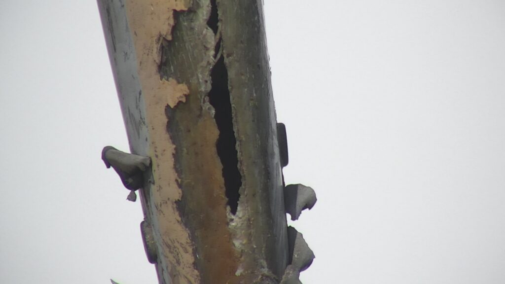
In the world of wind energy, a common challenge faced by wind turbine operators is leading edge erosion. This phenomenon refers to the gradual roughening of the leading-edge surface of the turbine’s blades, which can cause reduced performance and ultimately lead to costly repairs. Leading edge erosion is caused by the impact of particles in the air with the surface of the blade. Rain is often the main culprit behind erosion, particularly in areas with high levels of precipitation. However, other atmospheric particles such as dust or hail can also contribute to erosion. Over time, the repeated impacts can cause material to be removed from the leading edge, leaving a rougher surface than before. Preventing leading edge erosion is crucial for maintaining optimal performance and prolonging the lifespan of wind turbines. Operators may implement measures such as regular inspections, Leading Edge Protection shells. By understanding and addressing this common issue, wind farm operators can help ensure their turbines continue to generate clean energy for years to come. The power of rain and rotational force. Wind turbines operate in a variety of weather conditions, and precipitation is a factor that can have a significant impact on their performance and maintenance needs. Due to the rotation of the turbine blades, the blades can encounter more precipitation than what is registered on the ground. For example, consider a wind farm with an annual accumulated precipitation of 0.7 meters. An average rain droplet falling at a velocity of 6 meters per second will collide with the blade as it moves at 90 meters per second. This results in an accumulated amount of water impacting the leading edge of the blade of 10.5 meters per year. In contrast, the speed of the droplet hitting the ground is typically much slower, at around 22 kilometers per hour (or 16.67 miles per hour). However, the blade hits the water droplets with much greater force, reaching speeds of up to 324 kilometers per hour (or 201.32 miles per hour) when the turbine is operating at rated speed (Source) This discrepancy in speed can explain why some areas experience more leading edge erosion than others. Wind farm operators must account for this phenomenon when designing and maintaining their turbines to ensure optimal performance and minimize maintenance costs. By understanding the impact of precipitation on wind turbines, we can continue to improve their efficiency and sustainability in the years to come. Why is erosion problematic? Wind turbine blades are carefully designed with an optimized aerodynamic profile to maximize their ability to harvest wind energy. However, leading edge erosion can gradually degrade the blade, reducing its efficiency and ultimately lowering energy production. To compensate for the erosion, wind turbines may pitch the blades to maintain performance. However, if erosion is not addressed in a timely manner, it can directly impact annual energy production and result in costly repairs. This is particularly true if erosion begins to affect the structural integrity of the blade. Preventing leading edge erosion is therefore crucial for ensuring the long-term performance and sustainability of wind turbines. Regular maintenance checks can help identify erosion early on, allowing for timely repairs and mitigating the impact on energy production. Operators may also consider implementing erosion-resistant blade designs or protective coatings to help prevent erosion from occurring in the first place. By taking a proactive approach to leading edge erosion, wind farm operators can help ensure that their turbines continue to generate clean energy efficiently and cost-effectively for years to come. Some areas are more prone to cause erosion problems than others. Even wind turbines of the same type can exhibit different levels of leading edge erosion depending on the region where they are located. Wind farms are built in a variety of locations, including onshore and offshore areas with varying levels of precipitation. Some turbines may also have leading edge protection, while others do not. Research has shown that wind farms located in regions with frequent high rain rates and high wind speeds are more susceptible to leading edge erosion than those in areas with lower precipitation and wind speeds. This can have a significant impact on turbine performance and maintenance costs. To address this issue, our company collaborated with the Technical University of Denmark on a project called Blade Defect Forecasting. By combining meteorological data from the Danish Meteorological Institute, the expertise of DTU, and our own defect data, we created a machine learning model that can predict which areas are at higher risk of developing erosion. By leveraging this predictive model, wind farm operators can proactively identify potential erosion hotspots and take preventive measures to protect their turbines. This can help to reduce maintenance costs and increase the long-term sustainability of wind energy. What can be done to avoid leading edge erosion? There are several products available on the market designed to address the issue of leading edge erosion in wind turbine blades. These products can generally be classified into three categories: LEP shells, paint solutions, and tape. LEP shells, or leading edge protection shells, are designed to provide a hard and durable outer shell that can withstand the impact of airborne particles. Paint solutions, on the other hand, involve coating the leading edge of the blade with a specialized paint that can protect against erosion. Tape solutions typically involve applying a thin layer of specialized tape to the leading edge of the blade to provide additional protection. Each of these solutions has its own set of advantages and disadvantages. LEP shells can provide excellent protection against erosion, but they can be heavy and difficult to install. Paint solutions are lightweight and easy to apply, but they may require more frequent reapplication over time. Tape solutions are relatively inexpensive and easy to install, but they may not provide the same level of protection as other solutions. Ultimately, the choice of which solution to use will depend on a variety of factors, including the location of the wind farm, the severity of the erosion problem, and the operator’s
Internal inspections of wind turbine blades
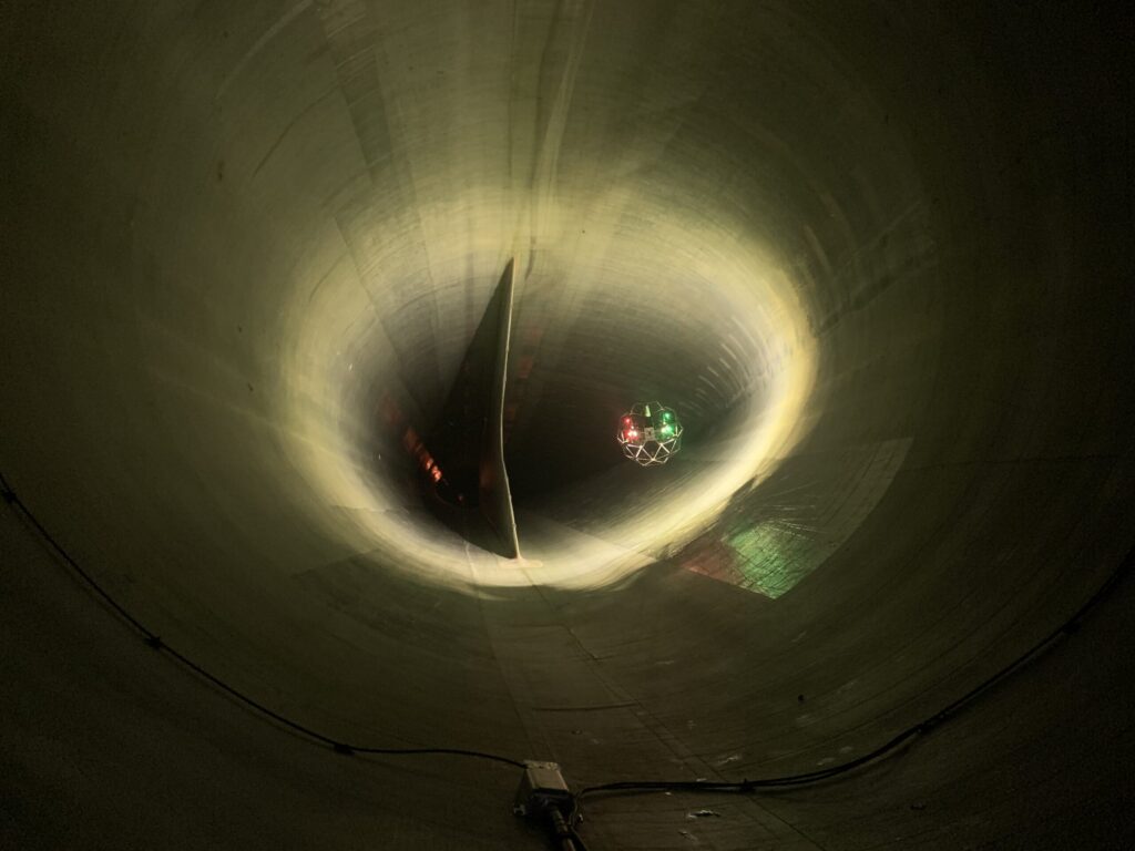
Why are internal inspections of your wind turbine blades important? Although external inspections of wind turbine blades are now faster and cheaper than ever before, there are still compelling reasons to invest time and money in internal inspections. Perhaps the most crucial reason is that certain types of damage to the blades cannot be detected from external inspection images alone. In fact, up to 90% of structural blade defects are only visible on the inside of the blade. This is especially important when the turbine is going out of warranty. From an economic standpoint, it’s crucial to document any necessary repairs or maintenance to avoid unexpected costs down the road. Even after the warranty period has ended, it’s essential to stay on top of the condition of the blades to prevent the development of costly structural defects. In short, while external inspections may be quicker and less expensive, investing in internal inspections is a wise decision that can help protect the longevity and profitability of wind turbines. Why use drones instead of sending in technicians to do the work? The use of drones for internal inspections is still in its early stages, but it’s an exciting development that has the potential to revolutionize the industry. In many ways, it’s reminiscent of the transition that external blade inspections faced when moving from rope access inspections to ground-based inspections. One of the key benefits of using drones for blade inspections is the improved coverage they provide compared to human technicians. With a drone, each inspection can cover all surfaces of the blade, including areas that are inaccessible to technicians. As a general rule, drones can reach up to 2/3 of the blade, although this can vary depending on the layout of the blade. Another significant advantage is the faster inspection speeds. Normally, it takes three technicians an entire day to conduct a single internal inspection. With drones, it’s possible to conduct 3-4 inspections in a single day, depending on the size and location of the turbine. Finally, using drones can reduce the need for technicians to work in confined spaces. Sending a technician into a confined space 100 meters (109 yards) above ground is not ideal, and drones can help eliminate this risk. Overall, while the use of drones for internal inspections is still in its infancy, it’s clear that there are numerous benefits to this approach. As the technology continues to evolve, we can expect to see even more exciting developments in this area. How is the drone inspection conducted? https://www.youtube.com/watch?v=Chk4Xjg054A Interested in learning More – Listen to the webinar about internal drone inspections https://www.youtube.com/watch?v=Sis3tf47ghA&t=207s Want to learn more? Don’t be a stranger – Feel free to reach out by clicking here