Search
Close this search box.

Wind Turbine Blade End of Warranty Best Practices

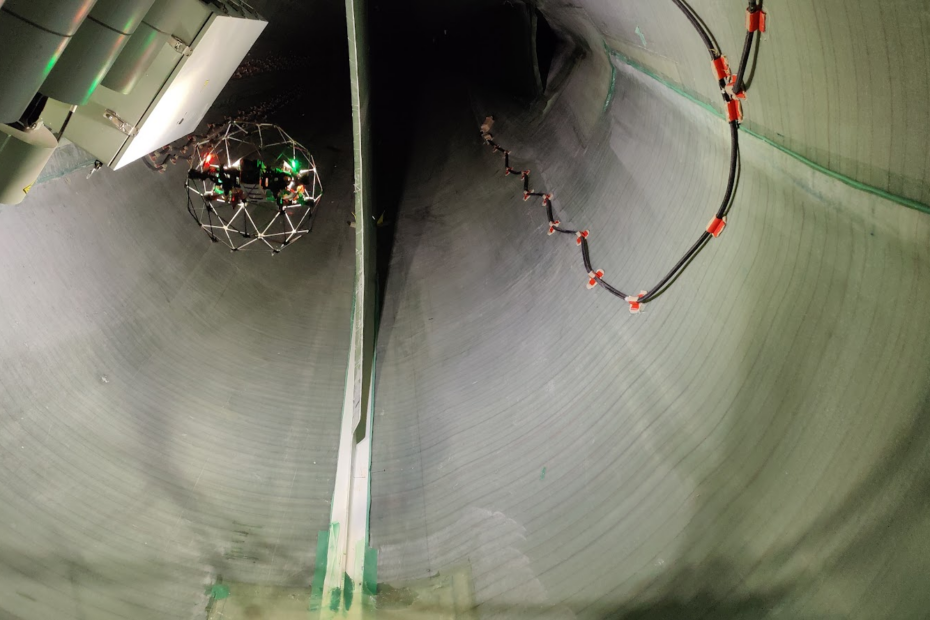
Internal inspection of wind turbine blade

Introduction End of Warranty (EoW) campaigns mark a crucial phase in the operational life cycle of wind turbines. These campaigns involve thorough inspections of major components, rectifying any defects to ensure that the turbine is handed over to the owner without significant damages. In this article, we will delve into the best recommended practices for planning and executing EoW campaigns, with a specific focus on wind turbine blades. Strategic Planning for EoW Campaign The planning for an End of Warranty campaign begins during the development phase, involving agreements on the warranty period after taking over the blades. Manufacturers may offer warranties ranging from 2 to 5 years. Planning is critical, with the inspection campaign ideally scheduled as late as possible within the warranty period. This allows for the development of more defects while still ensuring ample time for inspections and data analysis. Factors to Consider in Planning Lightning-Dense Areas: Schedule inspections during high lightning activity months to test the efficiency of the lightning protection system and address potential issues under warranty. Icing Potential Areas: Plan inspections after the second winter to test the de-icing/anti-icing system under operational conditions. This timing ensures coverage for potential damages caused by ice accumulation. Rain Event Seasonality: Observe as many rain events as possible before EoW inspections to analyze erosion development rates and assess the performance of the leading edge protection. Inspection Scope External Inspections External inspections provide a baseline for surface conditions, leading edge protection performance, erosion development rates, and detection of structural damages in the outer laminate layers. This includes assessing the lightning protection system, potential lightning attachments, and the condition of receptors and add-ons. Internal Inspections Internal inspections are equally important, detecting manufacturing nonconformities such as wrinkles and defects in adhesive bondlines. They also reveal early-life fatigue damages, including major cracks and delamination in inner laminate layers. Analysis and Maintenance Actions Once inspection data is collected, a thorough analysis is conducted to determine the most relevant maintenance actions for each damage. While the common approach is to repair defects during an EoW repair campaign, some defects may warrant a long-term maintenance plan between the owner and the manufacturer. Wind Power LAB can assist in producing claim documents defining the best recommended actions for each defect group, facilitating a smooth transition in the end of warranty claim documentation package. Conclusion End of Warranty campaigns are pivotal for ensuring the longevity and optimal performance of wind turbines. Strategic planning, comprehensive inspections, and informed maintenance actions are key elements in maximizing the benefits of these campaigns. For further insights and detailed discussions on EoW campaigns, reach out to our blade specialists at Wind Power LAB. Don’t be a stranger Feel free to contact us by clicking here

Can you control lightning risk?

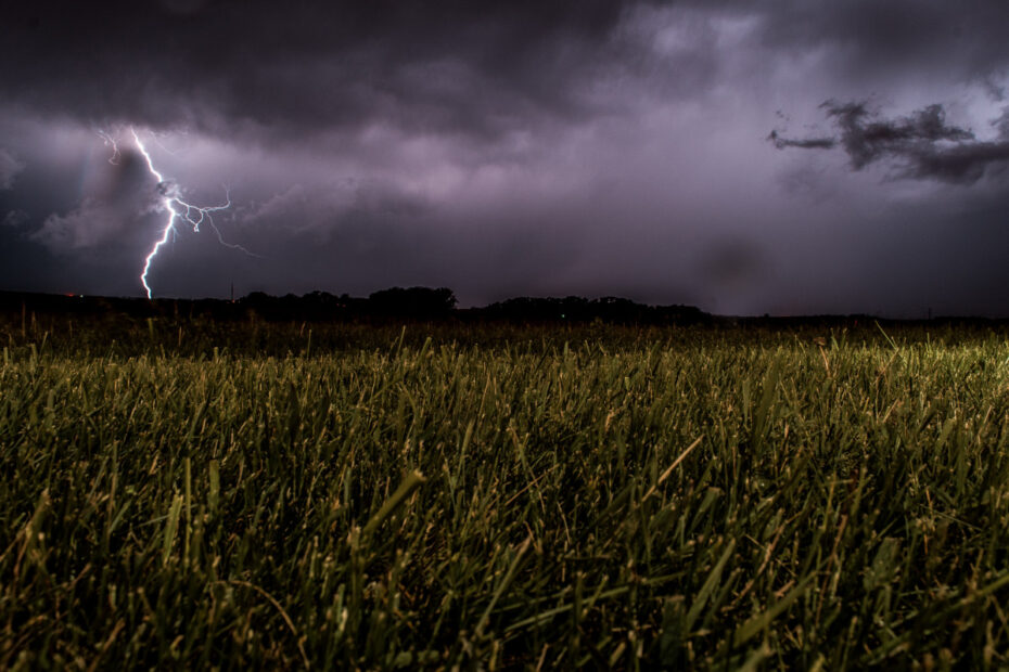
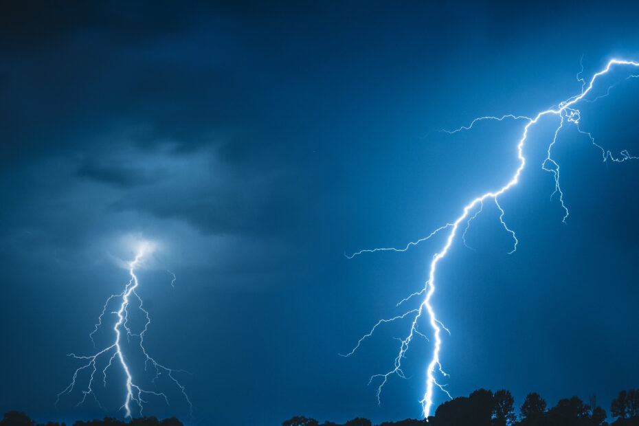
Harnessing wind energy is a remarkable stride towards sustainability, but it’s not without challenges. Wind turbine blades, reaching for the skies, face the potent force of lightning. These strikes can compromise blade integrity, affecting efficiency and safety. Innovative solutions are key – from integrating conductive materials to advanced lightning detection systems. This is where Wind Power LAB’s lightning surveillance service, LASSIE, steps in. By leveraging cutting-edge technology, LASSIE provides real-time monitoring of atmospheric conditions, offering crucial insights to operators. With lightning’s unpredictable nature, LASSIE empowers wind farms to make informed decisions, saving cost in operations after storms and minimising the risk of lightning-related damages propagating. By combining the might of wind energy with intelligent monitoring, we not only ensure uninterrupted power generation but also safeguard wind farm operation against the elemental fury of lightning. Together, we’re writing a sustainable energy future.  Want to get your wind farm under surveillance? It is easily done – The only thing you will need to do is click here  #RenewableEnergy #WindPower #Innovation #Sustainability #LASSIE

LIGHTNING PROTECTION SYSTEM (LPS)

The Lightning Protection System (LPS)  is a passive lightning protection, ensuring that lightning strikes hitting the blade are transferred to the grounding. The systems are tested in accordance to the IEC 61400-24 standard. Dependent on the test tier the system is designed to handle 100-200kA, without significant system wear. Receptors The receptor is a component made from metal like copper or equivalent current transferring metal alloy. It is designed to attract lightning and transfer the load to the receptor block. The receptor has a conic screw below the base that ensures contact to the receptor block. The receptor is a replaceable component that is mounted post blade production. On older blades the tip receptor can be a massive copper piece taking up the outer 20cm of the blade tip.  Risks of failure are worn receptor base or missing connection to the receptor block. The wear mechanisms include arching of the receptor base from lightning attachments and corrosion from water ingress between the receptor and receptor block. Visual inspection can be used to determine the condition of a receptor. Scorching and deformation are the most common signs of wear from lightning on the receptor base. Lightnings will also remove some material of the receptor base over time. If material removal proceeds below the blade surface, the receptor will have a reduced attractiveness to lightning.  Missing sealant allows water ingress between the receptor and the receptor block, which can cause corrosion and damage to receptor block over time.  Lightning Protection system receptor block ​To connect the receptor with the down conductor cable, an aluminum block is cast into the blade with the down-conductor during blade production. Replacement requires a complex laminate repair as the blade laminate must be removed before the block can be accessed. During post processing of the blade the receptor hole is drilled along with the thread for the conic screw.  ​Risk of failure is detachment or missing connection to down conductor cable or receptor. Missing connection to the receptor can be deducted from damaged or missing sealant around the receptor and corrosion of the two components. Another cause for imperfect connection between the block and the receptor is if the receptor has been screwed at an angle to the block, causing only partial contact, thus reduced capacity to safely transfer lightning. A missing connection between the receptor block and down conductor cable cannot be detected by a visual inspection. Instead, it can be checked with a resistance measurement. This type of check is recommended only as investigation to locate defect in a malfunctioning system and not as part of general inspection.  Down conductor cable The design of the cable varies between the different OEM’s, including copper mesh, solid copper cable, linked aluminum plates and solid cable.  The cable is centered on the web of the blade, it can be located on both LE or TE side dependent on the OEM design. The cable is cast into the blade during production. Repair is possible but very complex and due to a clamping device changing shape of the cable the blade has additional risks of wrong lightning attachments post repair.   If any carbon is used in the blade to increase the structural strength, it is important that the carbon is included in the LPS to avoid high difference in electric potential between the cable and the carbon laminate. If the carbon is not included, it must be thoroughly checked that it does not provide a risk of lightning jumping internally in the blade.  Failure types include missing connection to root terminal, or receptor block and cable separation due to fatigue. Connection to the root terminal can be checked with an internal visual inspection, which can be performed without entering the blade. Detecting separation of the down conductor cable is possible with a dedicated internal inspection. A skilled technician or internal drone can reach 1/3 into the blade, while a sewer crawler can inspect until a few meters from the tip. The most detailed inspection is achieved by a technician or drone inspection.   Root connection ​The root connection is designed to transfer the load from the cable to the bypass system. Blades are equipped with a slipring close to the root. The down conductor cable is connected to the slipring via a connection bolt through the blade laminate or via the backplate.  ​Failure modes at the root terminal include missing connection to the down conductor cable. If no connection is established lightning would seek other paths to the ground, risking damage to the laminate or drivetrain, which is not designed to carry electrical current.  Lightning transfer system ​The design of the transfer system varies between the different OEMs. It can be spring coupling, brushing, or spark gap. The brush and coupling designs are made to have as minimum partial contact from blade to grounding system at all times during operation. These systems are designed to receive limited wear from lightning transfer. The spark gap will transfer the load through an arch between the slipring and the lightning rod. Thus, significant wear could be expected, leading to an occasional need of replacement.  ​The defect mode that can be observed in the lightning transfer system is insufficient contact in the case of the brush or coupling, or too large distance in the case of the spark gap. In both ways the result would be a less effective, or completely dysfunctional LPS. Visual inspection can detect such defects, moreover for brush and coupling designs a resistance measurement can be performed, if there are doubts for the functionality of the system.   Lightning Protection System measurement The currently used method of determining whether an LPS is functional is by conducting a resistance measurement. It is performed by connecting multi-meter probes to the two ends of an LPS, essentially creating a closed circuit. To check the functionality of the system within a blade, you must connect one probe to the tip receptor and one probe to the root connection. To check the functionality on turbine level, you must connect one